Hi,
here´s one simple way to do it with an opamp.
(You´d only need the transmitter in figure1)
http://sound.westhost.com/project51.htm
You could also have a look at the BOSOZ from Nelson Pass but then you could omit your whole preamp. (nice article(s) anyway)
http://www.passdiy.com/legacy.htm
(balanced zen line stage; which is a class a preamplifier)
greets
Have a look at Rod Elliott's pages: http://sound.westhost.com/
Under Projects->Preamps and Accessories.
/Hugo")
Under Projects->Preamps and Accessories.
/Hugo
Hmmm the advice i was looking for was:
Buy this circuit board.
Solder the wires here, here AND here...not there though that would be silly.
Connect the power to the unit HERE and HERE.
turn on enjoy!
Could anyone offer advice on that level.
Sorry for sounding stupid, but lets face it I need lots of help!
Buy this circuit board.
Solder the wires here, here AND here...not there though that would be silly.
Connect the power to the unit HERE and HERE.
turn on enjoy!
Could anyone offer advice on that level.
Sorry for sounding stupid, but lets face it I need lots of help!
Ha ha... but this is Diy.
Let me try:
1) Get a board with those little holes in it or glue the chip to the chassis of the amp and go P2P.
2) Buy the chip mentioned by leadbelly
3) Buy 2 X 1µF cap.
4) Look for +/-15V or whatever the chip needs as supply in the existing amp. Alternatively you could fabricate a new supply but lets keep things simple.
5) Disconnect the output from your amplifier and connect it to the input of the chip.
6) Connect the output of the chip to an XLR.
7) Drill a hole in the back of your amp to fit the XLR.
Done.
Edit: Double the mentioned parts as this is for one channel.
10 caps? Hmm... where would you need them Pinkmouse?
/Hugo
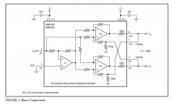
Use the DRV134. You will need the two chips, about ten caps, and about two square inches of perf board. You will also need to open up your pre, find the voltage rails for the preamp, and cut new holes for the XLRs. The last job will likely be the most difficult. If you give me a day or so I can draw you something up.
Netlist said:
Edit: Double the mentioned parts as this is for one channel.
10 caps? Hmm... where would you need them Pinkmouse?
2x 0.1uf + 2x 47uf supply bypassing, and, say, a 2.2uf dc blocking cap on the input, per chip.
The DRVs work best with good bypassing, as they have to drive lines they need a little attention in that area.
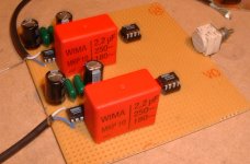
It's half a circuit I'm building at the moment - give me ten minutes and I'll post a pic.
Sure, take your timepinkmouse said:
It's half a circuit I'm building at the moment - give me ten minutes and I'll post a pic.
Re caps: I hadn’t looked at the datasheet, now I see.
/Hugo
Netlist, be fair. Surely you wouldn't recommend that as a first DIY project. Isn't that what they invented the phono amp for, the newbies?
And I know you weren't too serious. But I just had to add my 2 cents. I think it's great that people try to do whatever they can themselves. Of course, if pinkmouse posts that pic (edit: done) it just shows what great place this is for people with silly questions like me.
And I know you weren't too serious. But I just had to add my 2 cents. I think it's great that people try to do whatever they can themselves. Of course, if pinkmouse posts that pic (edit: done) it just shows what great place this is for people with silly questions like me.
phn
I'll stick by my claim that this is very achievable, and the most difficult thing will be cutting the holes. For that you will need what is known as a cone cutter, drill pilot holes tom start, then open them out to the correct diameter with the cutter.
Thinking about it, you may not even need the 2.2uf caps, if you take a feed from the back of the existing phonos, then they are already likely dc blocked. So two little boards, with a chip and four caps on each. You can't get much simpler than that!
pinkmouse, from what I have read elsewhere (being that I still wonder why more phono amps aren't balanced), what you say sounds perfectly fair. I probably expressed myself wrong.
Doing the soldering and stuff isn't that complicated. That I'm sure Peter Scowcroft will work out. I surely didn't want to discourage anyone. My argument was rather that even when you guys are going out of your way to make it clear and easy, you still can be hard to follow for a newbie. (That was what my first post was about. I can't teach this guy anything. All I could do was to refer to a very newbie friendly page that helped me understand how this balanced thing works.) Of course, all we newbies have to do is ask. But sometimes it's not easy to ask since you don't know how to phrase the question. Other times you have to ask some silly thing just to reassure you understand even when you are pretty sure you do. And you really don't want to be a pain.
Sorry for getting longwinded.
phn
Your comments are very valid, and I understand what you mean. Although I may sometimes look like I know a lot, I consider myself still a newbie to electronics, and I still ask some really stupid questions myself, for the same reasons you do.
So try to be patient with us, and we'll try to be patient with you. Deal?
- Status
- This old topic is closed. If you want to reopen this topic, contact a moderator using the "Report Post" button.
- Home
- General Interest
- Everything Else
- XLR modification