kambule said:Rodolf,
Interested to see the active LPF clean up some residuals if the sound card output.
Do you mind to post the schematic of the active filter circuit ??
thanks in advance.
kb
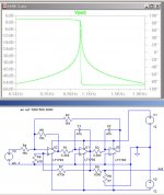
I do not have the original schematic files since it is a very old design (over 15 year back), so attached is a new one on LtSpice and simulation.
The actual circuit measured in the previous post includes a couple of modifications:
1. Devices are 3 parts from a OPA4134, and the spare one is connected as inverting unity gain buffer at (Out).
2. Resistors R1 and R2 are 10 turn 5K potentiometers.
Care should be taken as usual with grounding, power supply decoupling etc.
Rodolfo
Attachments
Re: Waveterminal 192L performance
Obviously a much better sound card Ashok
Rodolfo
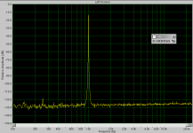
ashok said:Here is the FFT of a Waveterminal 192L sound card. Card OUTPUT to card INPUT.
44.1Khz/16bit/32.7Ksamples/Hanning/ 1volt
Not sure what the input impedance is. Probably 10 K ohms.
Obviously a much better sound card Ashok
Rodolfo
........measure the magnitude of the spurs.....
Yes that would be nice if I had the notch filter .
I was actually going to put up another FFT with a bandpass filtered signal with the same card. I couldn't because I can't locate the dual opamp ( AD826) 9v battery run circuit board.

I will find it soon and put up the FFT for comparison. IIRC it measured lower than 0.001 % with the filter. Could have been about 0.0003% or so and also with a slightly cleaner looking noise floor .
About measuring the amplitude of the spurs. The software has markers that can measure it directly as seen on the FFT.
I like to avoid as much labour as possible ! Another filter board....

Cheers.
apart from using standalone audio spectrum analyzer,
which pc software recommended for audio measurement.
Freeware is best.
My belief is an external usb soundcard (box) is better than internal one.....considering the pc switching power supply noise. However, seeing the FFT of waveterminal soundcard, I change my mind. Any comment please ??
thanks
which pc software recommended for audio measurement.
Freeware is best.
My belief is an external usb soundcard (box) is better than internal one.....considering the pc switching power supply noise. However, seeing the FFT of waveterminal soundcard, I change my mind. Any comment please ??
thanks
kambule said:Freeware is best.
Is that a statement of fact, or merely your opinion.
just starting to play with the iPod shuffle I bought this week to test a 12 bit adc with - the shuffle output goes as low as you want - I've put 1 Hz sq, tri in r,l channels of a 16-bit 48K .wav file (created .wav in LtSpice bv source .wave cmd, load into iTunes>Shuffle) - no output coupling cap - no droop, just a few % gain loss when driving into 32 Ohms
for sine distortion I looked at a 800 Hz sine + dither .wav played back thru Shuffle into esi Juli@ soundcard set for 24 bit 192K gives -93 dB 2nd, -99 dB 3rd harmonics (10 sec record to reach below the noise)
refurb 1st gen iPod Shuffles are <US$40
for sine distortion I looked at a 800 Hz sine + dither .wav played back thru Shuffle into esi Juli@ soundcard set for 24 bit 192K gives -93 dB 2nd, -99 dB 3rd harmonics (10 sec record to reach below the noise)
refurb 1st gen iPod Shuffles are <US$40
I use internal pci-soundcard with very good results.
The trick is to not use full scale signals and avoid the internal resampler of the soundcard.
This way i got perfectly clean fft plots, no harmonics visible. (below noise floor)
The signal source was goldwave, using the expression evaluator you can generate any testsignal you want. (Don't forget to manually add dithering) Playback was 24bit,48khz.
FFT plot also 48khz, 32768 window size, blackman, averaging = 10.
The soundcard is M-audio delta 24b96.
With this setup i can perfectly measure amp output, clearly seeing only harmonics created by the amp.
Attached is fft of cable loop back, output to input, no extra hardware.
Here is rmaa plot.
Mike
Attachments
jackinnj,
excuse for my poor english. I dont mean the performance, I only mean I am a poor guy....for freeware I dont need to pay.
MikeB,
Do you mean the generator is from : www.goldwave.com ?
How about the FFT program, which one you use ??
I think I still prefer external USB soundcard(box) because I am going to use portable computer.
thanks everybody.
kambule said:jackinnj,
excuse for my poor english. I dont mean the performance, I only mean I am a poor guy....for freeware I dont need to pay.
It was my fault, I was in a cranky mood yesterday evening.
kambule said:
MikeB,
Do you mean the generator is from : www.goldwave.com ?
How about the FFT program, which one you use ??
Yes, i meant that software, of course goldwave is a complete wave editor, the evaluation processor function is quite nice for test signals.
The fft plot was done with spectralab, used for educational purposes only.
I don't know if there is a freeware realtime spectrum analyzer.
Mike
Mike:
I looked at your plots from RMAA and they don't make a lot of sense. The SN numbers don't match the graphs or some of the other numbers.
I think the performance of the card should be closer to .001% THD+noise (or -98 dB). Actually the card should do .0008% or less if its typical of the class.
The unusual number is the difference between A wtg and wideband noise. That should be much greater.
-Demian
Yes, i was also confused by the data from RMAA, but the noise reading is correct. A full scale white noise shows spectrum of only -43db (at this samplerate). Because of that you have to add that to the noisefloor.
120-43 = 77db = 0.014% -> THD+N ??? But this would make the THD+N number questionable ? A noise floor of -120db is quite standard.
Mike
120-43 = 77db = 0.014% -> THD+N ??? But this would make the THD+N number questionable ? A noise floor of -120db is quite standard.
Mike
Anyone tried this circuit ??
http://www.redcircuits.com/Page82.htm
Total harmonic distortion @ 1V RMS output:
Frequency Reading
100Hz = 0.0035%
300Hz = 0.0028%
1kHz = 0.002 %
3kHz = 0.002 %
10kHz = 0.001 %
http://www.redcircuits.com/Page82.htm
Total harmonic distortion @ 1V RMS output:
Frequency Reading
100Hz = 0.0035%
300Hz = 0.0028%
1kHz = 0.002 %
3kHz = 0.002 %
10kHz = 0.001 %
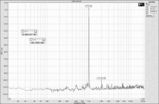
Here is the FFT from a Waveterminal 192L with a bandpass filter between output and input loop. I gave you the direct connection FFT plot in an earlier post.
The bandpass filter is a second order filter using a single NE5534 with +/- 9 volt battery supply.
OK the plot looks bad. Fundamental is at 1 volt ( 0db) and 2nd harmonic is at -102db .
Note: The filter center frequency is not 'exactly' at 1Khz. Its slightly less than 1Khz. So with a properly ajusted filter you might get the second harmonic down by about 2 db more , which will be -104db = 0.00063% .
The 0.00147% reading on screen includes all harmonics ( till the 9th I think ).
-102db is = 0.00079% .
Attachments
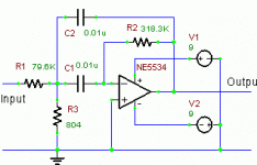
Here is the filter I used.
Opamp is NE5534.
All resistors are made up of two in series to get a fairly accurate value. Best method is to measure the capacitor values and then calculate the resistor values.
I did not use a dc decoupling input capacitor and the output had a 100 ohm resistor . Supply was from two 9 V batteries through 22 ohm resistors in each supply line and a 220uF capacitor for decoupling at each supply terminal on the chip.
Attachments
ashok said:Here is the filter I used.
Opamp is NE5534.
All resistors are made up of two in series to get a fairly accurate value. Best method is to measure the capacitor values and then calculate the resistor values.
I did not use a dc decoupling input capacitor and the output had a 100 ohm resistor . Supply was from two 9 V batteries through 22 ohm resistors in each supply line and a 220uF capacitor for decoupling at each supply terminal on the chip.
Again -- try the passive notch -- then you can isolate the problems not related to the fundamental -- this is a modified version of the one which Cyril Bateman used in his capacitor distortion series of articles in EW - the closer you match the components the better the notch -- this shows 54dB on the bode-plotter.
An externally hosted image should be here but it was not working when we last tested it.
A clarification................
I think my point has been missed.
I was trying to create as pure a test signal as possible so that any distortion generated by the DUT will stand out very clearly.
The test tone generated by the sound card is filtered to produce an even cleaner signal as demonstrated in the previous post.
This signal is the input for the DUT.
If the target was to look at the spectrum of the DUT then supressing the fundamental of the output of the DUT is a great idea.
Ashok, the fundamental may look pretty, but what you really want to examine is the magnitude of the harmonics -- by using a passive notch fitch filter you get the harmonics out of the noise -- everyone knows that the fundamental is there, but the 3rd, 4th etc. are in the noise. passive means that you don't have to concern yourself with the opamp running out of gain(although you do have insertion loss).
i understand the point you are making wrt use of a bandpass filter -- easier if you just use a Butterworth or Bessel low pass filter, however...if you have line problems consider a 400Hz high pass filter.
fwiw, i've never seen an analog THD analyzer without the residual function, at least for HP, Tektronix, Boonton and Krohn-Hite.
Jackinnj I do get your point. Yes I could have used a LPF . I tried the bandpass because on another sound card in another computer I get mains supply harmonics. Earlier I had a two opamp filter . I decided to see how good a simple single opamp bandpass would look.
You musn't forget that the aim of my exercise is to get a 'very' pure sine wave to feed into the DUT.
This might be a silly question. The software can track the harmonics and display their individual level . So would it be necessary to notch out the fundamental ?
My need for a pure fundamental signals was so that on an FFT I can see no visible harmonics ( below -120db? on my setup) . Then the output on a DUT can cleary show what it's generating even if it is at a low level. I can easily get the level of the harmonics even without notching out the fundamental. Am I missing out on something by thinking this way ?
Sorry, but I think you still didn't get the purpose of my circuit. I understand all you say , but I just want to get a very clean signal from the output of my sound card . That's all.
Thanks for taking your time to post a reply.
Cheers.
Cheers.
- Home
- General Interest
- Everything Else
- Low Distortion Signal Generator