I just won this on eBay and I can use it for parts or make it work with parts from one of the other parts units I have. But this will force me to sell some of my other distortion analyzers. EBay may get the highest price but also the highest hassle factor....there is a malfunctioning # 1110 on ebay now (270191162219)
Here is a link to the thread: Analyzers
Re: CFG253
Sorry for the post necromancy... I fully realize that you posted this nearly three years ago, but did you ever get the service info for the CFG253 from this guy? If you did, and still happen to have it, I'd be eternally grateful if you would share a copy with me!")
EchoWars said:Interestingly enough, I was able to find an older gentleman who did contract work for Tek back in the day, and still has complete information on the unit, as well as his own adjustment procedures, worked out after repairing dozens of these things. He has promised me that he will get them copied and sent. Very cool.
Sorry for the post necromancy... I fully realize that you posted this nearly three years ago, but did you ever get the service info for the CFG253 from this guy? If you did, and still happen to have it, I'd be eternally grateful if you would share a copy with me!
I just received an
"AMBER 5100 Programmable High Performance Audio Generator. Ultra-low distortion sinewaves (-106dbV THD+N), 10Hz-110kHz. Balanced and single-ended output with 50/150/600 Ohm impedances, self-cal function, GPIB "
--------------------
I don't have the manual.
It works, but freq is off by about 50Hz @1k, and the buttons stick a bit.
My dist. test measures at 0.05% at 1k, 1v.
(should be lower, no?)
---------------------
I opened it up, and on the oscillator board there is a "bulging" electrolytic cap (100u 25v).
I marked the polarity of the cap, removed it, and noticed the "board marking" does not coincide with the way the cap was installed (polarity).
As installed, negative went to ground.
As marked on the board, positive is to ground.
This looks to be the original factory cap.
This cap comes off a 311 comparator's VEE pin (-v), and goes like this:
VEE pin - thru a 100 ohm resistor - thru this bad cap - to ground.
So if it's coming off the neg voltage rail, positive should go to ground.... Does sound right?....and it was installed wrong at the factory ?
=RR=
Here's another Low Dist Oscillator....
Radford LDO Series3
http://www.amplifier.cd/Test_Equipment/other/radford.htm
Radford LDO Series3
http://www.amplifier.cd/Test_Equipment/other/radford.htm
I should have more results for an easy bandpass filter to lower distortion of a .01 % source in a couple days. This technique was already reported by another post above.
It easily takes a .01% source to .002%, maybe more. To build it you need one op-amp, 2 caps, and 3 resistors to make the circuit. Surprisingly, or not, I could not get an AD797 to work in it without oscillating. The oscillation made huge harmonics, which gave it poor performance compared to other op-amps. The basic circuit is here
http://sound.westhost.com/project63.htm
I tried two versions, Q=9, and Q=6. The Q=6 worked better. I used common values for all parts, carefully matching the two polystyrene .01uF caps. For about 2kHz, I used R1=47K, R2 = 680, R3= 100K.
It ended up being 1.91kHz. I determined this by feeding the sine source in to the filter then adjusting the frequency while watching the output on a scope. My source was an HP8904A.
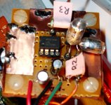
I use my ono sokki CF6400 to test a few op-amps. There was about 3dB difference from the best to the worst. The best were the LME49710, and AD847. After that, the OPA134, OPA604, and TI NE5534 were all also decent. Any of these would work fine, at least they did for me, without oscillation problems, in a fairly crude proto board. I used panasonic FM 33uf 35V +.1uF ceramic mono for bypass on +/- rails. Also used a copper foil ground plane. see pic below.
It easily takes a .01% source to .002%, maybe more. To build it you need one op-amp, 2 caps, and 3 resistors to make the circuit. Surprisingly, or not, I could not get an AD797 to work in it without oscillating. The oscillation made huge harmonics, which gave it poor performance compared to other op-amps. The basic circuit is here
http://sound.westhost.com/project63.htm
I tried two versions, Q=9, and Q=6. The Q=6 worked better. I used common values for all parts, carefully matching the two polystyrene .01uF caps. For about 2kHz, I used R1=47K, R2 = 680, R3= 100K.
It ended up being 1.91kHz. I determined this by feeding the sine source in to the filter then adjusting the frequency while watching the output on a scope. My source was an HP8904A.
I use my ono sokki CF6400 to test a few op-amps. There was about 3dB difference from the best to the worst. The best were the LME49710, and AD847. After that, the OPA134, OPA604, and TI NE5534 were all also decent. Any of these would work fine, at least they did for me, without oscillation problems, in a fairly crude proto board. I used panasonic FM 33uf 35V +.1uF ceramic mono for bypass on +/- rails. Also used a copper foil ground plane. see pic below.
Attachments
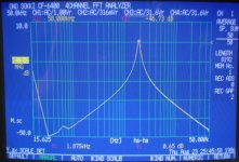
Below is a the log-log response of the first filter, Q=9, built with R1=68K, R2= 470, R3= 150K. Both used cap values for C of .01uF
The Q=9 version had slightly better measured attenuation, but had higher residual distortion on the initial readings made by the Ono Sokki 16 bit analyzer. I plan to use my M-Audio Audiophile 192 next and see how that fairs with internal and external sources.
Here's the attenuation measured at offset from fundamental where these harmonics would be
Q=9
2nd -21.3dB
3rd -26.2dB
4th -29.1dB
5th -31.3dB
Q=6
2nd -18.4dB
3rd -23.4dB
4th -26.3dB
5th -28.4dB
the Q=9 plot is below
Attachments
Here is the KH4400 (I haven't figured out how to attach two images to one post yet.)
Both read .0008% THD w/ 30 KHz low pass filtering, using inverting input and all of the other tricks I have figured out for lowest readings.
The display is 0-25KHz and the marker is at 2 KHz.
Krohn Hite:
I just picked up a Krohn-Hite 4400 -- plugged it in and was dis-heartened that the distortion was coming in around 6% -- so off went the lid -- I hooked up the oscillator to my Tektronix PS5010 and found that the distortion was 0.0008% with an external supply. The positive rail was also running "hot", there was a lot of ripple on both rails and the output was clipping under all circumstances. First thing I noticed were about a half-dozen 6.8uF 35V tantalum caps -- I replaced these with 100uF/100V Panasonics, replaced the filter caps (800uF Mallory's) with 1,000uF Panasonics, and replaced the positive 7815 regulator. Now the oscillator runs at 0.00022% when the 22kHz LPF, about 0.00046% with the 80kHz filter.
I had to pull out the Weller 1200 to solder this stuff up -- they weren't into dainty soldering pencils back in 1980.
Here's a comparison -- I bet no one has done this folks except, perhaps, the folks in Oregon --
The KH4400 has a bit of power supply noise, and the harmonics are 2nd order. The AP has no power supply noise, and the harmonics are 3rd order.
An externally hosted image should be here but it was not working when we last tested it.
The KH4400 has a bit of power supply noise, and the harmonics are 2nd order. The AP has no power supply noise, and the harmonics are 3rd order.
Re post 146 Radford LDO 3 :
The designer of this useful instrument, Jens Langvad, wrote a letter to Electronics and
Wireless World October 1987 p. 1030 :
"In the July issue, R. Shankar invites comments from readers to his proposed method
of obtaining a ripple-free, rectified output from a sine wave oscillator, for use in the
amplitude control circuit. A quadrature signal of the same amplitude is derived, the
two signals are squared and then added. Since sin2x + cos2x = 1, the output will be
d.c. proportional to the square of the peak amplitude.
This technique is not new; it is described in Burr-Brown's "Applications of Operational
Amplifiers" from 1972. I tried the idea a few years ago and found that in spite of its
apparent elegance, it is not a very practical method. As pointed out by Mr Shankar,
squaring circuits are expensive and, for a low distortion, they also require careful offset
and gain trimming, in order to completely balance out all a.c. components.
There is another principle, however, which may be put into practice without too many
problems. What is required is a voltage which represents the wave form amplitude,
which has no a.c. component in the steady state, yet still tracks the sine wave envelope
during transient states with a minimum of delay. These conflicting requirements rule out
the use of a straightforward rectifier. A sample-and-hold circuit, however, with a sine wave
supplied to its input, will store the peak value of the waveform if its control terminal is
driven by narrow pulses derived from the zero-crossing of a cosine (quadrature) waveform.
A fast-acting and accurate control loop is established as follows. The staircase envelope
supplied by the sample-and-hold circuit is subtracted from a d.c. reference. The difference
(the error voltage) is fed through a circuit which provides both the integral of the error
voltage and the error voltage itself, the sum of these controlling the loop-gain in the
feedback oscillator.
By properly choosing integration time and gain constants, the amplitude can be made to
settle within a few cycles of oscillation. With a well-designed amplifier, the distortion obtainable
depends solely on the linearity of the gain control element, and figures below -90 dB (0.003%)
are not unrealistic.
The principle described here was first put into commercial use in the Radford Low Distortion
Oscillator (type LD03) which I designed in 1972. This instrument was based on the parallel-T
resonator while subsequent versions have employed the more modern state-variable filter
structure, still with a sample-and-hold control loop."
This remark may also be useful in context of the large thread
https://www.diyaudio.com/community/threads/low-distortion-audio-range-oscillator.205304/
For a later private model of his oscillator JL claimed THD+N of 0,0006% (about -104 dB),
"mainly noise anyway".
Wireless World and many other interesting magazines from the past can be found at
https://www.worldradiohistory.com/index.htm
- Home
- General Interest
- Everything Else
- Low Distortion Signal Generator