Hey guys, just need some help with a simple (hopefully very simple amplifier).
Heres the story.
I have signal which oscillates between +1.0v and gnd.
I need to boost this to +12V and gnd.
As this is for use in the car, I can only supply 12V DC.
How do I go about this?
The phase of the signal is not important.. so I guess I could use an inverting opamp with 12k feedback and 1k input resistor (to obtain an overall gain of 12)?
But what about my supply rails? Can this be achieved if I only provide +12v and gnd?
Or is there an easier solution all together?
Any help would be appreciated, and thank you in advance!
Well, its not quite audio related, but can be applied in the same manner I spose.
I have a trigger signal from the ECU in a car, which is a square wave that swings from 1V to gnd, and has frequency between 15hz and 120hz.
I want to use this signal to drive a tach, but that requires a 12v to gnd swing for it to work.
I was thinking that a simple opamp circuit would do the trick in providing the necessary gain.
Just not sure how to go about it (and what type of opamp to use), especially because the car only supplies 12V DC.
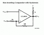
OK. You want a comparator,which is an op amp specifically made to switch between high and low based on an input signal being above or below a reference voltage. Your reference would be, say 0.5VDC (two resistors will give you this).
Check out the LM193 comparator datasheet (national.com). Note it uses positive, not negative feedback, in order to switch quickly and not oscillate its output if there is noise on the input.
Check out the LM193 comparator datasheet (national.com). Note it uses positive, not negative feedback, in order to switch quickly and not oscillate its output if there is noise on the input.
Attachments
Appreciate all the help Paul.
Ok, I've drawn it up in spice and I've attached the schematic I have.
Not sure what value resistors to put in R1, R2, R3 and or to calculate those values.
You can ignore the opamp I used in the schematic - couldn't find anything else in the library ; )
Thanks again.
Ok, I've drawn it up in spice and I've attached the schematic I have.
Not sure what value resistors to put in R1, R2, R3 and or to calculate those values.
You can ignore the opamp I used in the schematic - couldn't find anything else in the library ; )
Thanks again.
Attachments
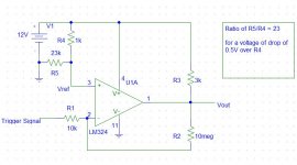
I think you want the values of R4 and R5 reversed so you get 0.5V relative to ground i.e. across R5. Maybe make R4 & R5 a potentiometer instead so you can adjust it for best output.
Also, reverse the + and - inputs to the comparator/opamp - you want positive feedback. Note this means the amp runs at a very high gain, which is what you want.
Paul
Also, reverse the + and - inputs to the comparator/opamp - you want positive feedback. Note this means the amp runs at a very high gain, which is what you want.
Paul
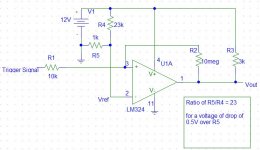
Forgot about the +/- terminals... wasn't paying attention heheh..
Heres the corrected schematic...
Will use a pot for R4 and R5.
Also took into account your recommendation of using 0.5V relative to gnd.
Does everything else look right?
Will implement this with an LM393.. which should be the same as an LM193 I think.
Heres the corrected schematic...
Will use a pot for R4 and R5.
Also took into account your recommendation of using 0.5V relative to gnd.
Does everything else look right?
Will implement this with an LM393.. which should be the same as an LM193 I think.
Attachments
- Status
- This old topic is closed. If you want to reopen this topic, contact a moderator using the "Report Post" button.
- Home
- General Interest
- Everything Else
- need a simple amplifier