Considering that lightning season is upon us here in Australia I've decided to make my own lightning arrestor using expresspcb and some copper pcbs using the toner transfer method and an online project:
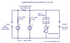
Lightning/Surge Protector Circuit Using Gas Discharge Tube (GDT)
Was wondering if there is anyway that I can improve the circuit to make it stronger and last longer or if its good enough as it is. I thought that the S20K250 MOV was rated a bit low? Any thoughts?
This circuit is designed for a 240v mains.
Attachments
Last edited:
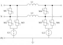
Found a better circuit with better protection:
A circuit simplification for AC power supply surge protection devices | EDN
A circuit simplification for AC power supply surge protection devices | EDN
You are on a 240v system, right? The improved circuit you linked was for 120v systems in the USA. In our system we have neutral and hot. The neutral is bonded to earth in the service panel at the building power entry. So unless there is a fault, neutral is essentially ground. That is why they got away with a MOV across and only a spark-gap to earth.
If I am not mistaken, your 240v system has neither leg tied to earth. So two hots. Yes? So you need not only the MOV across, but I would think still protection to ground from each leg.
If I am not mistaken, your 240v system has neither leg tied to earth. So two hots. Yes? So you need not only the MOV across, but I would think still protection to ground from each leg.
You are on a 240v system, right? The improved circuit you linked was for 120v systems in the USA. In our system we have neutral and hot. The neutral is bonded to earth in the service panel at the building power entry. So unless there is a fault, neutral is essentially ground. That is why they got away with a MOV across and only a spark-gap to earth.
If I am not mistaken, your 240v system has neither leg tied to earth. So two hots. Yes? So you need not only the MOV across, but I would think still protection to ground from each leg.
Right. I'm in 240v land.
I'm considering copying this design and using 250v rated components from the first schematic (GDT UZ470B & S20K250) that I posted in the first post. Let me know if there is any issues with doing this.
If anyone has a better circuit then please post it here.
Attachments
Last edited:
Earthing system - WikipediaAustralian and New Zealand standards use a modified PME earthing system called Multiple Earthed Neutral (MEN). The neutral is grounded(earthed) at each consumer service point thereby effectively bringing the neutral potential difference to zero along the whole length of LV lines
Also: What is Multiple Earthed Neutral? - Electrical Engineering Access
Last edited:
I think you use the word "think" to often to mess around in this filed. Go to your outlet shop and make a purchase.
//
And how am I supposed to know if its not just some cheap and nasty MOV-only surge protector? Open it up and then return it huh?
Maybe your right, then again once I learn this I can build it and know that the quality is good. But everywhere I look even online there is nothing but **** quality surge protectors.
There was a mains filtering circuit published in a silicon chip magazine in the 90s but I don't think it has much in the way of protection. I'll go and dig it out of storage.
Last edited:
This isn't the one that I mentioned in a previous post but it sure does seem promising (its not a surge protector, it has one VDR.):
Silicon Chip Online - 240V Mains Filter For Hifi Systems
Silicon Chip Online - 240V Mains Filter For Hifi Systems
Last edited:
I'm going to get royally screwed buying expensive surge protectors only to find out that they don't have GDT in them. Anyone know if APC surge protectors have GDT's?
APC SurgeArrest Surge Protector - High Quality | eBay
APC SurgeArrest Surge Protector - High Quality | eBay
specs on this unit say its only got MOVs and there is no mention of any GDTs: APC SurgeArrest 6 Outlet w/ Phone, Protection PH6T3-AZ | eBay
SurgeArrest components such as MOVs and Thermal fuse ensure instantaneous reaction to lightning strikes and wiring faults. If the surge components are damaged due to power spike or over voltage, excess power cannot reach your equipment. Unlike the APC SurgeArrest products, most surge suppressors continue to let power through even after circuits have been damaged, leaving your equipment exposed to other damaging surges.
Looks like I'm giving up on making my own and simply buying this:
DTA 1 Power Line Filter | eBay
http://precisionpower.com.au/pdf/PP-cat-2005-p16-1.pdf
DTA 1 Power Line Filter | eBay
http://precisionpower.com.au/pdf/PP-cat-2005-p16-1.pdf
Last edited:
If I am not mistaken, your 240v system has neither leg tied to earth. So two hots. Yes?
Almost certainly, his power is one leg earthed. "Somewhere".
However lightning surges are not susceptible to simple analysis. The rise-time is very rapid. The 50 feet from my house to the dirt-rods at my pole induces only 0.1V at 60Hz 100A but MUCH more for 30,000 Amps and 1-10us risetime (~~50KHz).
The EDN article is thought-provoking, but theorizes on cost reduction, and I don't see that it has been tested in lab or in field?
I like to theorize but I go with commercial products which have recognized testing.
You seriously want some SERIES impedance. Often this is factored as the impedance of the circuit wires.
You seriously want multi-level protection. I have a suppressor in my fusebox as well as at key appliances. Useful technical/sales sheet.
You seriously want to bond ALL your incoming wires together (per local laws and customs). I was losing two modems every summer, because the phone was overhead and the power was underground. The best path for induced aerial surge was through the modem. This would have helped. Also this. Properly installed!
If you are on a well there are other details. The pump is by far the best ground around the house.
Attachments
Last edited:
specs on this unit say its only got MOVs and there is no mention of any GDTs:
A GDT alone should never be used Line-Line. Once triggered they are effectively a short.
An MOV has the nasty habit of catching fire when hit with a big surge. You need to use a thermal fuse in series or have a way of isolating the MOV from anything flammable.
Most surge protectors are junk. Even the average whole house type and even many "Industrial" Surge Protectors. The MOV they use are fairly wimpy and cannot handle the surge. One big surge and they die.
Last edited:
The UK (230V) has Neutral bonded to earth on the box. There should be no more than mV difference between earth and neutral anywhere in the house. I think this is now the norm in the UK.
If you have ever seen the results of a lighting strike on power cables you would give up pretty quickly on micky-mouse DIY solutions!
If you have ever seen the results of a lighting strike on power cables you would give up pretty quickly on micky-mouse DIY solutions!
Last edited:
......neither leg of 240 is really neutral.
Define "Neutral".
Conceptually, a neutral has no load current.
This actually happens on fully balanced 3-phase loads.
However it is common to find lower-volt loads on one leg of 3-phase to "neutral". Now there is current in Neutral.
The US domestic system is a sub-sub-set of such a system. One phase as two opposite 120V legs supplied from a CT winding. Large loads may be taken off as 240V (and no CT current). Small 120V loads are tapped both 120V legs, and on average "tend to cancel" (no CT current), but never do sum to zero in real life.
So in practice "Neutral" is a word that leads to confusion.
What we may really be asking is: is one of these wires tied to DIRT ?
100 years ago, it was argued that un-grounded systems were safer. Easy to show in the lab. Practical men knew that no real system can be un-grounded; there's always leakage ample to electrocute. Also lightning WILL find dirt, so giving it multiple local dirt-rods tends to localize damage and minimize the extent of blackouts.
"ALL" utility systems are tied to dirt somewhere.
(An interesting exception is inside steel mills, a rare case where grounding clearly increases collateral damage.)
In US household power we about-invariably tie dirt-rods to that CT on the 240V winding. The power company at their transformer, and the house at the service entrance (supposedly).
(However it IS legal to have a sub-circuit which is _120V_CT. The idea is that this reduces the 60Hz field in the room and at your gear. 60VAC each side tends to cancel the electric field around the wires. Legal and should be safe. There is a case where another geek-mod disagreed with 120VCT and caused damage.)
In the UK the domestic power is almost always 240V with one side nominally tied to dirt and the other 240V hot. This is probably supplied from 3-phase Y transformers, houses distributed over the three windings semi-equally. The exact location of the dirt-bond is carefully specified between electric supplier and each unit. My impression is that UK suppliers tend to take responsibility for PE so that individual units do not have to.
However it is NOT technically required that one of your current conductors is tied to dirt. Only that some point in the system is. There are places with 3-phase Y and the CT tied to dirt, but loads fed from 2 of 3 Y-ends. You get 230V load voltage, both legs 132V away from dirt. Lightning will still find its way through the transformer insulation to dirt. No normal load should object to both legs live of dirt or Protective ground/earth. No load should be flowing significant current to PE except in fault. And in this case, the "Neutral" really does run zero-current so can function as PE without conflict.
Someone posited "mV" of N-PE potential. I can (in theory) show 22V of N-G potential worst-case (max load on one 120V leg, no load the other leg). That would be bad but unusual. However you can usually show half of the total line drop. Max line drop can be over 10%, so a 240V system will show 12V N-PE at full current. Less at normal currents. My house shows 1V-3V N-G most of the time. Not a dangerous voltage, but well up from Zero or mV.
- Status
- This old topic is closed. If you want to reopen this topic, contact a moderator using the "Report Post" button.
- Home
- General Interest
- Everything Else
- Making your own lightning arrestor.