Hi this is my first board ..made it with Eagle. Free version.
Any glaring mistakes in layout?
Where can I get boards made in Europe?
What type of file do boardmakers accept?
Tia.
Bas
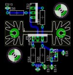
It is a high voltage CCS. Rev 4.d is essentially the design..only change is a pot with wire bridge so you can use either a resistor or pot.
http://home.zonnet.nl/horneman/mosfet.htm
Any glaring mistakes in layout?
Where can I get boards made in Europe?
What type of file do boardmakers accept?
Tia.
Bas
It is a high voltage CCS. Rev 4.d is essentially the design..only change is a pot with wire bridge so you can use either a resistor or pot.
http://home.zonnet.nl/horneman/mosfet.htm
Attachments
Let me tell you Bas ...
You'll never forget the first time")
What is it ? It looks like a CCS for tube gear. ( Edit: while I was asking you were still typing your post it seems ).
You can have the boards made by several companies in the Netherlands. They accept Eagle files in general and they love to produce quantities if you know what I mean. For a single board or a few you should inform carefully or find a small company that does not mind making a single PCB ( at a normal price ) for you between other runs.
I'll send you a PM if you want to know such small companies if you like.
You'll never forget the first time
What is it ? It looks like a CCS for tube gear. ( Edit: while I was asking you were still typing your post it seems ).
You can have the boards made by several companies in the Netherlands. They accept Eagle files in general and they love to produce quantities if you know what I mean. For a single board or a few you should inform carefully or find a small company that does not mind making a single PCB ( at a normal price ) for you between other runs.
I'll send you a PM if you want to know such small companies if you like.
Jean-Paul,
Yes please!
yep..it is a tube CCS.
Cheers,
Bas
I'll send you a PM if you want to know such small companies if you like.
Yes please!
yep..it is a tube CCS.
Cheers,
Bas
I've used www.olimex.com for 1 or two boards. The quality looks good and I've found no errors in the functionality. They are in Bulgaria. The prices including shipping are good even when you are as far away as I am (US). The website gives you all you need to know about files required, but check also their standard drill sizes and besure al the width of lines and text on the silkscreen meet their minimums -- they will fix these but for a price.
E$6 is shortened and you could arrange the connections a bit nicer (in line). The way E$11, 4, 5, 9 and 15 are connected looks a bit strange to me, but i don't know the schematics. Should there be a connection beteen 9 and 15 ?But why make a pcb for such a small pcb, veroboard could be used without problems (or is it high voltage?).
Olimex was fine the one time i used them (only ever made one pcb professionally).
mvg,
Thanks for the suggestions Sam and Guido...
Oeps...yes e6 is shorted..
I was thinking that 9 and 15 would connect since they touch?
Cheers,
Bas
Yes..quite easy to use veroboard. But was thinking of selling the board as well. But for instance I have to make around 5 for my phono amp alone... Also I was hoping that the boards will cause me to make less errors.But why make a pcb for such a small pcb, veroboard could be used without problems (or is it high voltage?).
Oeps...yes e6 is shorted..
I was thinking that 9 and 15 would connect since they touch?
Cheers,
Bas
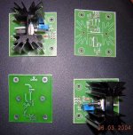
A real epoxy/fiber PCB looks nicer and more professional than Veroboard. Besides that the example you are showing seems more reliable ( heatsink can be screwed on the board for example ) and easy to mount with standoffs, something I would really appreciate when building a high voltage device. Security comes first especially when you want to sell these boards that cary lethal voltages !!! Be sure to include a small manual with the board with instructions. Let a non-technical person have a look at it for interpretation and don't be shy to include even the most basical advise like not touching the board when power is on etc. With this kit I would include all parts including standoffs so that there isn't an excuse for not using them.
Some people ( often the tube variety ) can have a strange way with electronics. I have seen tube-amps with bare wires running 500 V or more laying on the floor in a house where kids were playing and cats around ....
I guess boards of this size would cost you 1 or 2 Euro per piece when produced in larger amounts so in the end they may be cheaper as well ( I admit not knowing the price of veroboard ! ).
Maybe the left mounting hole could be a few more millimeters away from the heatsink ? ( just in case it has a voltage on it ). Overlooked the short on E$6...
Some people ( often the tube variety
) can have a strange way with electronics. I have seen tube-amps with bare wires running 500 V or more laying on the floor in a house where kids were playing and cats around ....I guess boards of this size would cost you 1 or 2 Euro per piece when produced in larger amounts so in the end they may be cheaper as well ( I admit not knowing the price of veroboard ! ).
Maybe the left mounting hole could be a few more millimeters away from the heatsink ? ( just in case it has a voltage on it ). Overlooked the short on E$6...
Hi Bas,
It's a long time since I used eagle, so I can't tell you where, but all schematic /pcb software has utilities for checking this kind of thing. generally:
Integrity: checks that PCB = schematic
Connectivity: All points are connected
Design rule: Short's overlaps, clearances.
These can be output from the PCB prog. It's normal to zip 'em up into 1 file for submission.
Make sure they all have the same time stamp (within a second or 2)!
Some PCB houses will extract these for you if you supply the .pcb file.
Oeps...yes e6 is shorted..
I was thinking that 9 and 15 would connect since they touch?
It's a long time since I used eagle, so I can't tell you where, but all schematic /pcb software has utilities for checking this kind of thing. generally:
Integrity: checks that PCB = schematic
Connectivity: All points are connected
Design rule: Short's overlaps, clearances.
All boardmakers accept gerber plot files. One for each layer of copper, one or 2 for solder resist, one or 2 for screen print (legend). Sometimes a board outline plot file too. Also a drill file.What type of file do boardmakers accept?
These can be output from the PCB prog. It's normal to zip 'em up into 1 file for submission.
Make sure they all have the same time stamp (within a second or 2)!
Some PCB houses will extract these for you if you supply the .pcb file.
dhaen said:
Some PCB houses will extract these for you if you supply the .pcb file.
Olimex accepts eagle files!
Updated
Mmm olimex looks good.
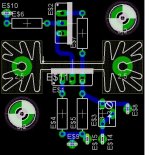
Updated schematic for a bigger heatsink sk129...smaller one will still fit sk104
Added some more connection points just in case..
Edit: Going to get 6 of these done for 35$. Not bat at all. Single sided with silk screen on FR4 material.. Plus they will be pre-cut. And including postage. From Olimex. I am very very satisfied with these folks. Very good email response and support. All I had to send in was the *.brd.
Mmm olimex looks good.
Updated schematic for a bigger heatsink sk129...smaller one will still fit sk104
Added some more connection points just in case..
Edit: Going to get 6 of these done for 35$. Not bat at all. Single sided with silk screen on FR4 material.. Plus they will be pre-cut. And including postage. From Olimex. I am very very satisfied with these folks. Very good email response and support. All I had to send in was the *.brd.
Attachments


- Status
- This old topic is closed. If you want to reopen this topic, contact a moderator using the "Report Post" button.
- Home
- General Interest
- Everything Else
- Suggestions on board layout