To package it - there are still unknowns:
- What is the smps you want to use?
- How about the output filter elements - they are crucial for audio quality and the few (passive) components in the filter easily use as much space as the rest of the parts - check out the millenium output filter, which you can find on the internet. They use two coils/capacitors (think they are from denmark), which are way bigger than the mosfets!
And their Power supply caps are bigger than the digital components.
But if you look at the TI sample boards your size requirements are not out of reach. Actually all that digital electronic can be made small so the constraint comes more from the mentiones analog parts and from power supply...
TNT,
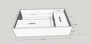
see the block diagramm with the connexelectronic power supply - which you mentioned in your picture and the TI TAS5261 example power stage. You see there's plenty of space in the housing to get the pwm stuff mounted....
I'm sure, if a real design is made then there is space for stereo setup (2x50W) in the same housing.
Attachments
... missed to mention that the tpa325 requires analog in - with all the losses inherent to analog and with the extreme long analog path you get from your audio controller...
NB: In my suggestion this long path carries PCM over toslink!
to be honest - I never compared a well designed analog-digital converter chain to a full digital chain with similar quality (design, components, manufacturing) so I cannot tell you. I listened to quite a few (different) analog A and AB amplifiers and I listened to well done pure digital amplifiers. A comparison with the same room, loudspeakers and audio material and with my own and known music material is something I would really like to do - but what I cannot afford to do (costwise and timewise!), not to mention the risk that I may end up spending lots of €€€€...
TNT,
see the block diagramm with the connexelectronic power supply - which you mentioned in your picture and the TI TAS5261 example power stage. You see there's plenty of space in the housing to get the pwm stuff mounted....
I'm sure, if a real design is made then there is space for stereo setup (2x50W) in the same housing.
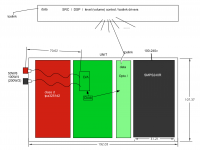
Yes plenty room! Even more if you use a complete class-d chip like tpa3251d2?
I feel that probably giving a comparable bigger chunk of the space budget to the output coils is probably a smart investment SQ wise. I must look these up!
You mention stereo - well if used as stereo (2 ch L/R) you get a long analog path again i.e. the distance between the speakers. You could build a 2-channel unit to drive say left channel bass and left tweeter from one unit. This brings us into the aspect of individual channel integrity (here channel mean left tweeter) - what happens to the tweeter signal when there is a big low frequency plonk in the left stereo channel - there will be interference - the is why I would like a complete isolated path for say bass and an other one for tweeter - still both carrying left stereo channel media albeit divided into different parts of the spectrum.
After these discussions I think I would like to move some stuff back to the controller and make the Unit:
- fixed gain
- no signal manipulation (as in filter or eq)
see pic.
//
Attachments
Last edited:
OK so I start to realize that with the PWN chip one can lose a discrete D/A block - right?
What I don't understand is if a D/A is still in there in these PWM chips or if in some sense they are bypassed with some other logic making it possible go from PCM or PWM in "one go".
Is it so?
//
What I don't understand is if a D/A is still in there in these PWM chips or if in some sense they are bypassed with some other logic making it possible go from PCM or PWM in "one go".
Is it so?
//
Well, go ahead with your design!
I, with my system, will avoid the long analog lines and avoid sending small signals of analog music to an amplifier with fixed gain and avoid multiple AD/DA conversions. Recommend you to take care to have a very high bit - depth in your TOSLINK to avoid that you limit the digital bandwidth when you turn the amp down...(see the reduced SNR when turning down the signal amplitude in the TOSLINK sender unit).
Another more practical thing is the electronic design. With the analog paths more than one analog voltage needs to be clean, very clean - otherwise the better coils won't help (and I agree that you spend as much as possible for these!)
Keep us posted about your design, please
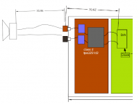
Hmm how can you state that? My drawing in post #24 show 70,62 mm of analog path ") probably a few centimeter more in reality. But still this must be regarded as very short - how can it be improved?
probably a few centimeter more in reality. But still this must be regarded as very short - how can it be improved?
I think it has bee proven by ESS and others that it is possible to create a very transparent digital level control so I'm not worried about that.
//
probably a few centimeter more in reality. But still this must be regarded as very short - how can it be improved?I think it has bee proven by ESS and others that it is possible to create a very transparent digital level control so I'm not worried about that.
//
Last edited:
The analog lines are most suceptible to pick up distortions.
To the 70mm of speaker wiring (with low impedance and high currents --> not very prone to pick up if done properly) you need to add the internal analog signal wiring. In case you send the data over TOSLINK (hopefully with full bit-depth), you then add a DA-AD conversion step. From my experience with electronic every step in analog gives losses - especially AD converters need a lot of effort (and experience) to make them good - on paper 24 bit components can be purchased but if you ever tried to make a nano-Voltmeter (with > 20kHz bandwidth and with two reference voltages (placed close to a smps)) you'll know what I'm saying.
And this means that not only the pwm-analog lines, also the real analog wires (and their voltage supplies!!) are extremely critical in your design.
So make sure your analog wiring is noise free, wires can't move, and everything is shielded. Also place all the components to regulate the analogs as far away from the smps and the mosfets as possible (which adds ~ 100 mm to your total analog length)!
I acknowledge there are concepts which work well - but we were looking for building blocks also providing flexibiltiy. And in my experience flexibility is not possible with accuracy in analog. Designs requiring < nV in analog signals in my experience always needed to be trimmed individually.
The signals most easy to copy is the digital toslink/spdif signal (but give some jitter). To put the DA conversion as close to the loudspeakers as possible and with the smallest amount of (low power) analog signals is probably the best way to provide immunity to distortions.
The weak spot in my all-digital architecture is the integrity of the pwm signals from the pwm generator to the power stage, therefore the design of my pwm board puts a lot of focus on this.
The ideal would be a I2S or spdif input high power MOSFET stage, but so far I didn't find a good component (maybe because of the DSP work needed???). There are some from TI but they all provide less than 100 W of power (and with (for my feeling) not-so-good MOSFETS).
I appreciate if somebody could mention other similar components (from other supplier).
To the 70mm of speaker wiring (with low impedance and high currents --> not very prone to pick up if done properly) you need to add the internal analog signal wiring. In case you send the data over TOSLINK (hopefully with full bit-depth), you then add a DA-AD conversion step. From my experience with electronic every step in analog gives losses - especially AD converters need a lot of effort (and experience) to make them good - on paper 24 bit components can be purchased but if you ever tried to make a nano-Voltmeter (with > 20kHz bandwidth and with two reference voltages (placed close to a smps)) you'll know what I'm saying.
And this means that not only the pwm-analog lines, also the real analog wires (and their voltage supplies!!) are extremely critical in your design.
So make sure your analog wiring is noise free, wires can't move, and everything is shielded. Also place all the components to regulate the analogs as far away from the smps and the mosfets as possible (which adds ~ 100 mm to your total analog length
)!I acknowledge there are concepts which work well - but we were looking for building blocks also providing flexibiltiy. And in my experience flexibility is not possible with accuracy in analog. Designs requiring < nV in analog signals in my experience always needed to be trimmed individually.
The signals most easy to copy is the digital toslink/spdif signal (but give some jitter). To put the DA conversion as close to the loudspeakers as possible and with the smallest amount of (low power) analog signals is probably the best way to provide immunity to distortions.
The weak spot in my all-digital architecture is the integrity of the pwm signals from the pwm generator to the power stage, therefore the design of my pwm board puts a lot of focus on this.
The ideal would be a I2S or spdif input high power MOSFET stage, but so far I didn't find a good component (maybe because of the DSP work needed???). There are some from TI but they all provide less than 100 W of power (and with (for my feeling) not-so-good MOSFETS).
I appreciate if somebody could mention other similar components (from other supplier).
As I hope could be seen from my drawing the 7 cm is from inside the Unit i.e. from somewhere within a DAC chip, out as a balanced analog line and into the power stage (internally PWM) and out to the terminals. Then we need to add an other 7 cm speaker wire to get within the goal of a total of 15cm analog path length.
Of course at this stage the cm and mm are only a mind game. This will probably not be met but to minimize this is one of my goals.
The electrical environment inside the unit will be challenging - high frequency switching at high voltages and currents at the same time as it shall house handling of very low signal levels in the D/A section. Most probably a set of inner shield boxes are needed and some very good isolation and buffering of the power feed to the D/A - yes!
I'm thinking of returning the clock form each Unit back to the controller so to make an synchronous relation between the two. The controller must adapt and pass the data to the Unit which should only have a very small buffer (a few words of data) to cope with any slip (that should not occur). This means double toslink per channel but 5 meter costs 5€. Cheeper than Nordost speaker cables.
I can live with an R2R DAC playing 16/44. I currently use a Soerkris DAC with digital volume control and it plays red book CD as a champ. It would be nice to split this into one part in the Unit and one in the Controller with the clock in the DA section fed back to the Controller for a synchronous mode of operandum between the 2 boxes.
I wich I could have some useful input to the PWM solution you are seeking but I'm afraid I don't have the insight to do this. I hope that your reached out hand is responded to by those who master this.
Now just some small realization work remains :-D
//
Attachments
I pop up in the conversation, that I find very intreresting. I found the thread while working on ideas for a 2 ways loudspeaker whith fully digital amplification and DSP based cross over.
I was looking for a clean, efficient and cheap solution. Try to avoid problems at the source when possible. Use software when possible for price and flexibility. I'm more a software guy and integrator. I don't have knowledge for designing hardware boards.
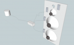
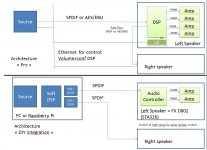
I have identified below 3 architectures:
- cheap DIY: this is my (initial way). It should work, but not sure that it is the perfect one,
- the pro one: in fact the one used for Genelec and TwoTwo professional speakers. It looks pretty close from the proposal from TADigital, except for the chaining of the SPDIF
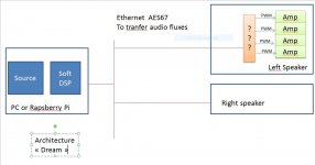
- my dream option: all fluxes developped on the CPU, and then send to amps using AES67 (audio over Ethernet) with a RJ45 network. Unfortunatly, I haven't found AES67 chips (only quick search)
Note the STmicro provides really interesting single chips. The STA326 included in the D802 chinese amp, had a lot of buzz in France some tipe ago, and in one chip you can have several inputs, mixing, DSP, ans several amp configs. Not bad at all
Comments welcomed !
JMF
I was looking for a clean, efficient and cheap solution. Try to avoid problems at the source when possible. Use software when possible for price and flexibility. I'm more a software guy and integrator. I don't have knowledge for designing hardware boards.
I have identified below 3 architectures:
- cheap DIY: this is my (initial way). It should work, but not sure that it is the perfect one,
- the pro one: in fact the one used for Genelec and TwoTwo professional speakers. It looks pretty close from the proposal from TADigital, except for the chaining of the SPDIF
- my dream option: all fluxes developped on the CPU, and then send to amps using AES67 (audio over Ethernet) with a RJ45 network. Unfortunatly, I haven't found AES67 chips (only quick search)
Note the STmicro provides really interesting single chips. The STA326 included in the D802 chinese amp, had a lot of buzz in France some tipe ago, and in one chip you can have several inputs, mixing, DSP, ans several amp configs. Not bad at all
Comments welcomed !
JMF
Attachments
Last edited:
Ethernet to I2S; Not Cheap, but this is the type of interface I would appreciate in the dream architecture:
AVB OEM kits : AVB-DG
However, this AVB device requires a dedicated switch.
JMF
AVB OEM kits : AVB-DG
However, this AVB device requires a dedicated switch.
JMF
Nice to see some more people contributing to the thread. Yes, the STA326 is interesting. Would be interesting to hear a minimalistic but skillful implementation using this chip in mono configuration. Good clock (scheme), separate regulators for each voltage pin and a good SMPS power source. I would prefer opto links compared to ethernet for sheer size and bulk of cables feeding a multichannel (6-8) system. By "fluxes" you mean stereo or single channel?
http://www.st.com/web/en/resource/technical/document/datasheet/CD00062804.pdf
//
http://www.st.com/web/en/resource/technical/document/datasheet/CD00062804.pdf
//
In my "dream" architecture, I mean "audio fluxes". In fact in that case, the speaker would be connected only to:
- 220V,
- 1xEthernet RJ45 to send from the central CPU all audio channels directly to the amp (Volume, crossover, DSP...) done on the central CPU.
I don't think that optic link adds anything in a house, with small distances. Ethernet is more than proven for data transfer. And if well designed can cope to some level with real time applications like audio.
JMF
Ok, I'll try to be more precise.
Let's imagine a 4 ways loudspeaker. I want FDA (full digital Amp) for each driver, installed inside the speaker. I want to have a digital signal up to the input of the FDA (full digital Amp).
On the computer, ALL the processing. The computer calculates each channel of 2x4 drivers (L+R)x4 drivers.
This would mean 2SPDIF per speaker. Instead, I propose to have the audio of the 8 channels go over ethernet to the speakers like on an office network.
I call above each data stream a "flux":
- Tweeter L
- Mid L
- Woofer L
- ....
- Tweeter R
- Mid R
- Woofer R
- ....
For sure, it needs a specific protocol to keep all those data synchronized: AES67 or AVB.
As I'm looking for a cheap lean solution, for example using a 30$ Rapsberry Pi, I can't build my design on lot of I/O, like 4xSPDIF.
The only largely available interface is USB, but I'm afraid (maybe without reason) of the ability of such architecture to maintain 4 USB audio streams synchronized.
I think that ethernet over mains is more problems than benefits. I like ethernet cables for their reliability.
JMF
OK re "flux" but to be really sure: the audio of the 8 channels go over ethernet -> the audio of the 8 fluxes go over ethernet?
So this is exactly what I want to do conceptually. Maybe we have some different idea how to implement in detail but the basic architecture is identical.
But an ethernet based protocol is interesting. In order to only need to run 1 cable per speaker there is a need for a local switch when L/R has more than 1 channel i.e not a single driver loudspeaker.
//
Last edited:
That this the magic of digital: one "cable" multiple information. On the same ADSL line, you can have TV + Phone + internet +...
You need juste to select the right hardware media + the right protocol. The issue from my perspective if that the protocol could be AES67. However it has only been finalized in 2013 for professional applications. So it is not maintream, so it is a little market, so there are not a lot of products and tehy are expensive.
Mainstream: HDMI: one cable = 8 audio uncompressed PCM channels (cool !). There is an HDMI cable on all computers and media player. This could prove really cost effective.
HDMI cable to the first speaker, that uses channels 1 to 4. Then the HDMI cable is daisy chained to the second speaker that uses channels 5 to 8.
In each speaker, an HDMI decoder decodes the audio channels to I2S then PCW to power part.
I imagine that a good HDMI cable can be as long as 3m.
JMF
Isn't HDMI under heavy licensing? = Expensive. I'm personally not so keen in HDMI. 3 meter is not enough for me.
What is a good HDMI cable? One that dosen't change bits? Staying digital, cables should not matter beyond information integrity. AES67 might even have resending?
Personally I would not mix a lot of ordinary, heavy, bursty TCP/UDP traffic in a AES67 network - just to be safe.
They claim 10ms accuracy. While that may be enough for accuracy when deciding when to insert a picture or a sound flux into a mix, I seems borderline for splitting one and the same flux into two, say LF and HF (2way speaker) and keep the 2 synchronous enough to not being audible. I read that the ear-brain can detect 1-10 ms. I would like a safety margin by 10 here.
I'm not an EAS member so I don't have access to the specs but for the moment I regard this as an media distribution and mixing framework. I'm dubious how it would cope with the test case:
1) Take three analog line level pairs each carrying very low distorsion 1khz sinus signal (from ore and the same source) and feed it into three A/D converters, each connected to the AES67 NW.
2) Also, on the analog side of A/D converters, sum the 3 analog signals into one (A-Sum)
2) Send, over the EAS67 NW, the 3 fluxes to three D/A converters.
3) Sum the 3 converted fluxes into one 1 kHz signal (D-Sum).
4) Subtract the A-sum form the D-sum
What is the result? Distorsion? Not until I saw the result would I dare to put my money on this system for my intended application. Timing is everything
This test needs to also to be subject to different NW events and loading and need to be observed over a longer time I believe.
I believe a toslink network would perform superior to an EAS67 based one in such a test as the one described above. I also believe the EAS67 was not designed to cope with this kind of application. What puzzles me is that PTP and nano second accuracy is mentioned... just name dropping or?
//
Last edited:
- Status
- This old topic is closed. If you want to reopen this topic, contact a moderator using the "Report Post" button.
- Home
- General Interest
- Everything Else
- Interface juggling and function topology adventure.