I haven't looked at the PAM8403 but I think you can get a bass boost through the feedback loop. I'll look later.
My recent project has four 1 1/2 inch drivers and 2 60 x 920 mm passive radiators. No matter what the weight of the passive radiators is, there is no dip whatsoever in the speaker output at the passive radiator resonance. Could be the 2.2l box is too big or the speaker compliance is too low.
Sent from my SAMSUNG-SGH-I537 using Tapatalk
When I dissect/rebuild a unit, I try to copy the size/volume of the original fixture. I figure the guys that designed it knows a lot more than me. (Especially if ya can't find any T/S information on the drivers)
I haven't ventured into passive radiators yet. Messed around with some ports. Personally, I like sealed enclosures better..
As for full range drivers, I've been playing around with a baffle step compensation circuit. Applied it to a set of 5" ElCheepo single driver Sony book shelf speakers. Changed them from ear rippers to something not so bad to listen to. A definite improvement. Might add a tweet to get some sparkle back..
I believe 2.2L is a lot of internal volume for those little drivers. I doubt if there's enough air compression for the passives to make any difference..
What are the dimensions of the original enclosures? Those water squirtin' speakers ain't very big..
I think the water speakers had a volume of .12 liter, sealed (laugh) for 1 speaker. This is obviously too small but I do think mine is too big. I re-measured and it's actually 1.8 liters or closer to 1.7 with battery and bracing. I bought this one because it had a handle and looked about right for what I wanted. There were no numbers to crunch.
I played around with passive radiator weight again and I think I found out why they don't resonate as much as they should. The surround is very stiff rubber. The original metal plates were 36 grams. I'm using wood plates that weigh about 10g. The metal ones resonated at 55 Hz, which didn't work at all for these tiny speakers. The resonance is around 110Hz now and the drivers resonate at 180 Hz. This gives it one last hump before falling off below 100 Hz. It really doesn't sound bad. Beats the heck out of my little wally-world speaker that is supposed to be a Jambox knockoff. It also has one 3W amp per speaker so it's loud enough for its intended use.
As for sealed boxes, I prefer them for serious use. I have 4 original Advent Loudspeakers behind me. I also have some old Electrovoice, Boston Acoustics, and KLH knockoffs that are sealed. My car subs are usually sealed too, except for the off-the-shelf ones I added to factory stereos.
OK, I see what you mean by baffle step compensation. That's sorta what I was thinking about doing with the amplifier negative feedback loop. I'm assuming yours are passive inside the speaker. If you are attenuating everything but low frequencies, you might try adding a small capacitor to the circuit so that the highs at tweeter frequencies would not be attenuated. Do you have a schematic for your circuit?...As for full range drivers, I've been playing around with a baffle step compensation circuit. Applied it to a set of 5" ElCheepo single driver Sony book shelf speakers. Changed them from ear rippers to something not so bad to listen to. A definite improvement. Might add a tweet to get some sparkle back..
Attachments
The circuit that I've been playing with is very simple. Resistance and Inductance. Totally passive..

All of the units that I build doesn't have much baffle area and always lacked the bass response that I wanted. This circuit has opened a new page in my search. I can adjust the response to the speaker from the amp via changes in inductance and resistance at the BSC circuit and adjust the crossover components with a more defined reaction..
I wouldn't laugh at the .12 liter of internal volume. That would be about right for a driver that small. A sealed enclosure needs to create some air compression to do its job. If there is too much volume in the enclosure there's little or no compression. The compression is what makes the passive radiators work..
Great idea. I must try that. Keeps it legal as a full range, I figure.. ")
Attempt to construct an enclosure around the size of the original and include a passive (If possible) and see what happens. Perhaps put two together in one enclosure and double the internal volume..
Running your drivers in series for 8 ohms won't increase the SPL but will increase the driver area by two. That should help with the low frequency response..
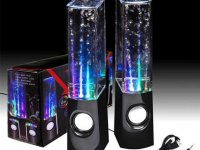
If I use 4 drivers, that would be .48 liter. The originals were plastic but they sounded too small. 1 liter might work better. In case you missed it, I used the amps from the water speakers too so I have a 3W amp for each speaker. They probably only put out 2W from 3.7V but there's not much of an issue with volume. Here is a picture of speakers similar to what I used.
Attachments
I was assuming 2 drivers in separate enclosures. (L&R) Connecting in parallel would take the impedance too low. (2 ohm) Connecting in series would be 8 ohms but you would lose some wattage but double the cone area per enclosure..
I assume its a quest for low frequency response. Mid/Highs should be ample for such a small driver..
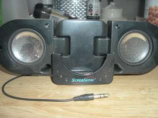
I tore one of these apart some years ago. Installed a voltage regulator in place of the battery (4 "AAA") to operate from my 12 v.d.c. house battery. (12 to 5 volt) Removed the speakers and extended the speaker wires from inside of the housing for the ability to connect to other speakers..
I assume its a quest for low frequency response. Mid/Highs should be ample for such a small driver..
I tore one of these apart some years ago. Installed a voltage regulator in place of the battery (4 "AAA") to operate from my 12 v.d.c. house battery. (12 to 5 volt) Removed the speakers and extended the speaker wires from inside of the housing for the ability to connect to other speakers..
Oh, I see. Either way, I have a stereo amp board for every 2 speakers so I sacrificed battery power and gave each speaker its own amp.I was assuming 2 drivers in separate enclosures. (L&R) Connecting in parallel would take the impedance too low. (2 ohm) Connecting in series would be 8 ohms but you would lose some wattage but double the cone area per enclosure..
Yes, basically a double jambox. I've even thought about adding 2 or 4 more speakers to the rear panel with a low pass filter. for more bass. Would make up for the oversize box, too.I assume its a quest for low frequency response. Mid/Highs should be ample for such a small driver..
I had one of those until someone stole it. I always wanted to build them a bigger enclosure.I tore one of these apart some years ago. Installed a voltage regulator in place of the battery (4 "AAA") to operate from my 12 v.d.c. house battery. (12 to 5 volt) Removed the speakers and extended the speaker wires from inside of the housing for the ability to connect to other speakers..
I had lots of enjoyment from that little amp. It's been used a lot and still keeps on tickin'..
Used it on a project with some small transducers. Wife brought home some tacos one night and challenged me to make the box produce sound.. LOL.. I did it! Bluetooth and all..
https://imageshack.com/a/XD0q/1
The amp in the box is the above after the mods. I powered it with lead acid 6 volt rechargeable lantern batteries connected in series for 12 volts. (This was before I discovered the 5 volt amps I currently use) Now everything uses 5 volt bank batteries..
Played around with some Memphis 3" dash mount speakers. I ported the box and added some BSC to it and it doesn't sound too bad..
http://imageshack.com/a/img901/1513/TMX4Fu.jpg
Used some bubble wrap and cotton batting to tame the cardboard down a little..
http://imageshack.com/a/img538/5115/TvqBgp.jpg
Gotta love playin' around..
Can't wait to see what you come up with. You might want to look at unfinished wood boxes at Hobby Lobby. Also, do you have any audio analyzer (RTA) software? There are a couple of free ones around that I have been using. I don't need accuracy so a decent computer mic works for me. I use it to find the resonance of drivers and compare the effects of changes like passive radiator weight. When I get a chance, I will post some general findings on micro stuff.
Sent from my SAMSUNG-SGH-I537 using Tapatalk
Sent from my SAMSUNG-SGH-I537 using Tapatalk
I don't have any testing ability at this point. Just my trusty VOM and my ears. I'm discovering what components does what. (chokes, caps, resistors, enclosure volume, ect..) Online design sites, my calculator, (this wonderful place) and my abilities are my tools. I plan to expand someday but for now, I enjoy playing midnight baseball..
I built a prototype last night with two 2.5" drivers that I recycled from a couple of Motorola console speakers and 2 ribbon tweets that were headed to the trash. I'll post a pic or two tonight..
I built a prototype last night with two 2.5" drivers that I recycled from a couple of Motorola console speakers and 2 ribbon tweets that were headed to the trash. I'll post a pic or two tonight..
OK, here is a little bit about micro speaker systems and how they use passive radiators to get more bass. I'm sure most people here are familiar with sealed and ported speaker design. A passive radiator acts similar to a port but doesn't take up space inside the enclosure, making it ideal for something very compact.
In most speaker designs, the fb or enclosure tuning will be higher than the driver's free air resonance or fs. Putting a speaker in a box raises its resonant frequency. In traditional speakers, this is very low at 20-50 Hz or so. The tiny drivers used in micro systems may start out with an fs much higher than that and the box will surely raise it. That's where the passive radiator comes in. What we do is tune the passive radiator lower than driver's resonance. As an example, we might use a 1 1/2 inch speaker with an fs of 120Hz and put it in a tiny enclosure. It will now resonate at 150Hz. If we add a slightly larger passive radiator and tune it to 100 Hz, we now have more bass extension, possibly to 80 Hz or lower. but at a lower level. Manufacturers usually use equalization or DSP to compensate for that.
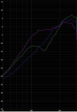
I took some crude measurements from a cheap speaker to illustrate it better. It has 2 2 inch speakers and a 3 3/4 x 3/4 inch passive radiator. The mic is very close. The green line is a main speaker. You can see the resonance at 270 Hz and a notch at 140Hz. The notch corresponds to the passive radiator's resonance shown in pink. The blue line is the main driver's response without the passive radiator. How much this helps and at what frequency isn't completely clear to me yet but my ears tell me there is more bass from 100 to 150Hz. This is probably higher than one would want, probably due to the main drivers' fs. I would love to see measurements like this from some good bluetooth speakers but I don't own any of them. Feel free to correct or add any information here, as I can't find any good information on the internet. I don't think manufacturers want us to know.
In most speaker designs, the fb or enclosure tuning will be higher than the driver's free air resonance or fs. Putting a speaker in a box raises its resonant frequency. In traditional speakers, this is very low at 20-50 Hz or so. The tiny drivers used in micro systems may start out with an fs much higher than that and the box will surely raise it. That's where the passive radiator comes in. What we do is tune the passive radiator lower than driver's resonance. As an example, we might use a 1 1/2 inch speaker with an fs of 120Hz and put it in a tiny enclosure. It will now resonate at 150Hz. If we add a slightly larger passive radiator and tune it to 100 Hz, we now have more bass extension, possibly to 80 Hz or lower. but at a lower level. Manufacturers usually use equalization or DSP to compensate for that.
I took some crude measurements from a cheap speaker to illustrate it better. It has 2 2 inch speakers and a 3 3/4 x 3/4 inch passive radiator. The mic is very close. The green line is a main speaker. You can see the resonance at 270 Hz and a notch at 140Hz. The notch corresponds to the passive radiator's resonance shown in pink. The blue line is the main driver's response without the passive radiator. How much this helps and at what frequency isn't completely clear to me yet but my ears tell me there is more bass from 100 to 150Hz. This is probably higher than one would want, probably due to the main drivers' fs. I would love to see measurements like this from some good bluetooth speakers but I don't own any of them. Feel free to correct or add any information here, as I can't find any good information on the internet. I don't think manufacturers want us to know.
Attachments
I started a build but got side tracked on another tangent. Planned to use a couple of simple Piezos but NOOO.. Wasn't good enough..
http://www.diyaudio.com/forums/everything-else/285235-piezos.html#post4580680
http://www.diyaudio.com/forums/everything-else/285235-piezos.html#post4580680
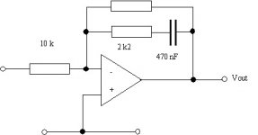
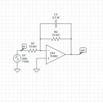
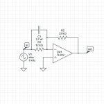
I mentioned earlier that I was trying to boost the bass a little electronically on my speaker shown in post 7. I may have found the answer. I also noticed that the highs went from dull to harsh depending on the position and angle of the speaker. I thought maybe the 2 left and 2 right speakers were the wrong distance apart. further reading told me it's a bad idea to have two vertically aligned drivers covering the same frequencies and that's what I was hearing. Since I have 4 independent amps, I decided to try a low-pass filter on the lower drivers. It's as simple as paralleling the negative feedback resistor with a capacitor. I only have a few spare caps lying around so I started with a .022 µf. I don't know the slope of the filter but that cuts 300 Hz by half. Well, the bass is quite boomy with these little drivers so now it is dominating the mids. The highs, however, actually sound brighter. Now I'm wondering if I should go lower to kill some of the boom or higher to let some midrange through. I do have to be careful that all 4 drivers are active in the low range because they share the same space.
It's not perfect but I have a decent sounding speaker now. I mentioned the low-pass filter on the lower speakers and high boost on the upper speakers. Well, the distance of the centers of the speakers equates to the wavelength of 5.7 kHz. In other words I need for anything above that to come from only one speaker to avoid the combing effect. I had very few spare capacitors in the range needed so I decided on .0027 µF, which I had 5 of. That gives a low-pass of 2.7 kHz and a high-boost of 4.9 kHz and up. I know the circuits could be modified a little better and the values fine tuned but the PCB uses SMD's and is very hard to add anything to and even harder to change components. It sounds pretty darn good with only a slight hint of combing. I made some quick diagrams of the mods below. The amps are LM4871, not TL082.
Attachments
- Status
- This old topic is closed. If you want to reopen this topic, contact a moderator using the "Report Post" button.
- Home
- General Interest
- Everything Else
- Which forum for mini bluetooth speakers