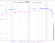
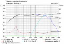
I am attaching measurements that show measurable influence of speaker cable to both frequency response and distortion. The speaker cable is a zip cord with 1.5mm2 cross section area and is 5m long. Frequency response and distortion are measured directly at amplifier terminals (blue) and also at speaker terminals behind the speaker cable (red). We can see that both frequency response and distortion plots are modulated by speaker impedance for the measurements behind the cable. 3-way speaker is used.
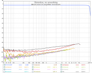
The amplifier itself has very very low output impedance. Its frequency response and distortion in fact copy those of the measuring card.
The amplifier itself has very very low output impedance. Its frequency response and distortion in fact copy those of the measuring card.
Attachments
Very interesting. A smoking gun for cables affecting response! And who knows what is happening at radio frequencies to cause oscillation? 
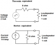
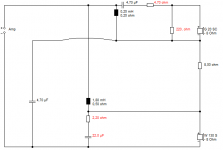
There's a school of thought that if you modify the speaker and filter so it presents a flat impedance to the amplifier, then an ohm or two resistive or even some reactance from the cable has very little effect. You can certainly model this by adding a series reactance or just 6 ohms, and some great speakers had a very flat impedance.
In fact once speaker impedance is flat, and TBH this is particularly difficult to do with the bass peak because the LCR has ludicrous values, it really doesn't matter if it's a voltage-source solid state amplifier or a current-source valve amplifier. Or what the cables do.
I'd hope you have seen the sort of LCR elements that are added to parallel crossovers to make them SET (non-feedback) valve-friendly and impedance flat. But maybe they are a good thing with solid-state amps too.
Attachments
Last edited:
Very interesting. A smoking gun for cables affecting response!
Nothing much new. I've cited the Davis and Greiner papers from 30-35 years ago numerous times. Pavel has added some distortion measurements (a nice idea), but those seem to be not normalized to the frequency response changes.
SY, you are mean!
We might as well give up now. Everybody wants a better speaker. My friend Cousin Billy is designing some really good stuff with series crossovers. The idea is that the damping doesn't rely on the amp, it's built into the speaker.
http://www.diyaudio.com/forums/multi-way/279278-4-way-series-crossover-accuton-acoustic-elegance-drivers.html
Are series crossovers special? I think they are. They have not only a shallower rolloff than parallel filters, they use a bell-shaped curve on the slopes, rather than the boxy quadratic function of parallel filters. The fact they do relatively flat impedance too is, well, INTERESTING.
Attachments
Last edited:
Pavel has added some distortion measurements (a nice idea), but those seem to be not normalized to the frequency response changes.
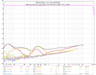
The plots of H2, H3 etc. distortions are with respect to fundamental. Yes the fundamental is modulated behind the cable, but within no more than 0.4dB, so the distortion plots are quite OK. The main reason of modulated distortion behind the cable is actually nonlinear speaker current (even if voltage is linear) times cable resistance. See also
Current drive of speakers and speaker distortion
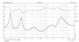
I should probably emphasize that both measurements are with amplifier loaded with speaker (+ cable), blue plot is directly at amplifier output terminals and red plot is at speaker box terminals. Speaker impedance is like this:
Attachments
With the at-the-speaker distortion test showing >80 dB down from the fundamental, I'd say that's nothing to loose any sleep over.
Sure, however it is interesting, at least to me.
Remember the amp has output impedance of some 0.005 - 0.01 ohm. What would you say if I used a tube amp with output impedance of 1 - 4 ohm?
Yes, cable influence would disappear but we shall have huge linear and nonlinear interface distortion, not mentioning intrinsic tube amp distortion.
You will see the same effect on the battery terminals and the starter motor when starting your engine. At the low impedance side of the conductor (resistor) you will see much less effect than that at the side that is transforming the electrical energy into mechanical energy with varying impedance.
Sure, however it is interesting, at least to me.
Remember the amp has output impedance of some 0.005 - 0.01 ohm. What would you say if I used a tube amp with output impedance of 1 - 4 ohm?
Yes, cable influence would disappear but we shall have huge linear and nonlinear interface distortion, not mentioning intrinsic tube amp distortion.
That might be more relevant and interesting because of almost the same impedance both sides of the speaker cable. Do you have a tube amp to try?
Sure, however it is interesting, at least to me.
Remember the amp has output impedance of some 0.005 - 0.01 ohm. What would you say if I used a tube amp with output impedance of 1 - 4 ohm?
Yes, cable influence would disappear but we shall have huge linear and nonlinear interface distortion, not mentioning intrinsic tube amp distortion.
Yes it was interesting and I support all DIY'rs to experiment with audio tests. You can do nothing but learn more about this wonderful hobby.
Keep up the good work.
Last edited:
Frequency response and distortion are measured directly at amplifier terminals (blue) and also at speaker terminals behind the speaker cable (red).
Hi PMA, interesting results. On some distant past thread I showed similar frequency response measurements for 18 gauge as I recall. Two questions:
- what is the nominal impedance of the 3-way?
- is the input stage of the measurement system referenced to ground?
I remember in my communication days that we used impedance correcting networks every few km of telephone cable to correct for line distortion and group delay. One would expect the distortion to be horendous after a few km of two core copper, but it was not. You would still recognise your mother from your wife.
Remember the amp has output impedance of some 0.005 - 0.01 ohm. What would
you say if I used a tube amp with output impedance of 1 - 4 ohm? Yes, cable influence
would disappear but we shall have huge linear and nonlinear interface distortion,
not mentioning intrinsic tube amp distortion.
All of John Atkinson's Stereophile amplifier tests include frequency response into a dummy speaker load.
Check out some of the no-nfb tube amps.
Last edited:
OK, we can see that the cable makes a measurable difference. It will, of course, depend on cable resistance and inductance, though capacitance would have a negligible effect for the low Zout and stable amplifier.
Now, how about audibility? I assume that measurement of some phenomenon is a basis of further discussion on possible audibility. If we had zero measurable effect, the speculations about audibility would be difficult
Now, how about audibility? I assume that measurement of some phenomenon is a basis of further discussion on possible audibility. If we had zero measurable effect, the speculations about audibility would be difficult
https://passlabs.com/articles/speaker-cables-science-or-snake-oil
seems unlikely that reasonable speaker wire resistance/impedance converting dynamic speaker nonlinear currents is going to be more than a 1 dB add on the same nonlinear current flowing in the voice coil R/Z
you do select your cable to be < 10x speaker nominal Z?
seems unlikely that reasonable speaker wire resistance/impedance converting dynamic speaker nonlinear currents is going to be more than a 1 dB add on the same nonlinear current flowing in the voice coil R/Z
you do select your cable to be < 10x speaker nominal Z?
Last edited:
OK, we can see that the cable makes a measurable difference. It will, of course, depend on cable resistance and inductance, though capacitance would have a negligible effect for the low Zout and stable amplifier.
Now, how about audibility? I assume that measurement of some phenomenon is a basis of further discussion on possible audibility. If we had zero measurable effect, the speculations about audibility would be difficult
Audibility? At >80 dB down (0.01%!) from the fundamental; if you can hear that, you are awarded 'golden ear' status.
The Newell/Holland experiments with loudspeaker cable/loudspeaker combinations and amplifier/loudspeaker combinations are still interesting....
Loudspeakers: Effects of amplifiers and cables - Part 5 | EE Times
Loudspeakers: Effects of amplifiers and cables - Part 5 | EE Times
Hi PMA, interesting results. On some distant past thread I showed similar frequency response measurements for 18 gauge as I recall. Two questions:
- what is the nominal impedance of the 3-way?
- is the input stage of the measurement system referenced to ground?
I posted the impedance plot, nominal impedance is pointless.
Measurement is balanced.
- Status
- This old topic is closed. If you want to reopen this topic, contact a moderator using the "Report Post" button.
- Home
- General Interest
- Everything Else
- Measurable influence of speaker cable to freq response and distortion