rif:
I think you've basically got it right: Volts x Amps x Power Factor = Watts.
Power Factor is always between 0 (for a pure reactive - inductive or capacitive - load) and 1.0 (for a pure resistive load), although 0.5 is pretty low - what kind of load is that, and how are you measuring it? I've got a "Kill A Watt P3" that does a nice job of measuring such parameters as well as accumulated power consumption (Watt-Hours); unfortunately it only works through 120V receptacles, so measuring hard-wired loads like lighting is more involved.
At least in this part of the world and for small residential customers, the power company meter measures Watt-Hours, and billing is for same. Hence, (Volts x Amps) - Watts is not directly billable, but costs the power utility nonetheless due to resistive line losses upstream of the meter. It's been a while, but I do seem to recall that larger Industrial/Commercial customers are charged a stiff penalty for - among other things - lower Power Factor loading, so I believe that's primarily the saving incentive addressed by Power Factor correction devices, as mentioned by Pano.
Wilf
For a capacitor-based power supply i.e. most electronics, the textbook power factor figure is around 0.6 or 0.66. And the bigger your capacitor bank is, the lower the PF goes.
Which is why PFC is mandatory in EU countries. With APFC, computers have a PF of approximately 1.0.
Audio equipment? I'd say 0.5, or less.
Which is why PFC is mandatory in EU countries. With APFC, computers have a PF of approximately 1.0.
Audio equipment? I'd say 0.5, or less.
I think domestic electric meters measure watts with the assumption that Power Factor is 1
I think that means we get any reactive current for free.
An example would be a mains powered LED bulb with a small capacitor providing the main voltage dropping reactive element. The remaining substantially resistive loading of maybe 6V to 12V is the "watt" measured power consumption.
Can someone confirm any of that?
The common household mechanical meter is designed to measure watts. There are meters that are designed to measure VA too. With the electronic meters, it's whatever.
If the electricity gets converted into other form of energy instead of being sent back to the grid, you will get charged for the watt regardless of how you got it.
Using capacitors to form a voltage divider to drop AC voltage is an old concept, which is abandoned because of safety reasons and because it plain sucks. Electronics do better job cheaper and with PFC.
In the earlier days of efficiency and attempting to out do the opposition, Hitachi Electronics produced as they called it, a Watt-less Power Supply that ran the standby supply for the microprocessor and IR receiver on one of there TV's. This used a 220nF Class 2 capacitor feeding the usual shunt rectifier with a regulator that fed the Microprocessor etc. In those days we had the mechanical type Magnet/Aluminium reacting clock work meters and they didn't detect out of phase power. (Very useful then but no longer as they are electronic now). Before that manufactures of Strip Lighting fitted a, (for a 2foot lamp a 2uF) parallel capacitor. All this did was to align the power drawn by the strip lamp back in phase with the mains supply, otherwise the meters didn't go around!
Things have moved on from the old days of free power!
Things have moved on from the old days of free power!
Your utility meter measures true watthours. It does not assume power factor is 1, it responds to the torque impressed on an induction disc, which is proportional to power. As the disc rotates in time, it integrates and turns (ratchets) a numerical register which records watthours. Not VA, actual power.
Power factor as typically referenced is defined as the ratio between W and VA. There are new power factors, such as displacement, fundamental, and true, that have arisen with the acknowledgement of harmonic effects, but the OP question is more simplistic. So for now we will stick with the óld' definition of power factor.
If you have a 120V load that is running 5A at 80% power factor, the VA is 600, and the watts is 480. Utility meter will respond ONLY to the 480 quantity.
If you have a 120V load that is running 5A at 100% power factor, the VA is 600, and the watts is also 600. Utility meter responds to the 600 quantity.
Residential customers do not get penalized for poor power factor. Larger industrials do, normally when either demand load has reached a minimum threshold or if they are primary rate (incoming service greater than 600V). Fundamental reason for this is that the utility must accommodate the VA (not watt) load when sizing transformers and lines. VA load is always equal or greater than watt load.
Also, power factor penalties are only charged when the power factor is lagging, or inductive in nature. Capacitor power supplies and drives, which may present leading power factors, do not create a penalty. Large industrials install power factor correction capacitors within their facility to bring a severely lagging power factor to a less lagging condition. If they correct too much and lead (say 90% leading), utility does NOT charge for this power factor. Reason is that the customer is providing VARs to the grid for free, and they thank you very much for that.
Not to overburden the discussion beyond what the OP has questioned, but one more note on how PF is measured for a primary rate customer. It is beneficial to discuss how this was done in the old days, rather than how A/D and microprocessor meters do it today.
There are two watthour meters installed. One measures watthours. The other one is prefaced with a set of phase shifting transformers to apply a 90 degree phase shift to the voltages. When this is done, the second watthour meter now becomes a VAR-hour meter (not a VA-meter). It is of the ratcheted induction disc type, such that the disc cannot spin backwards. It therefore accumulates lagging (and only lagging) VAR-hours. If a customer consumes a bunch of VARs, then a minute later sources a bunch of leading VARs, you do not get those lagging VARs back. The disc is ratcheted.
Each of the meters are equipped with KYZ outputs and demand accumulators which are synchronized to measure over a time period. Typically 15, 30, or 60 minute intervals. Each 15 minute period, there will be a dataset of total watthours and total VARhours in that 15 minute period.
The power factor is only considered for one single 15 minute period: when the maximum demand is reached (as determined by a maximum 15 minute watthour accumulation). At that period of time, the power factor is determined from the 15 minute watthours and 15 minute VARhours for only that single 15 minute interval. It is a calculation to determine power factor, as Whr and VARhr are orthogonal to one another.
Point being, the utility only cares about power factor when demand load is at its highest. This is reasonable, as it is the limiting condition that they must size their equipment to handle.
When was it abandoned? I have at least two items in my house, both bought within the last 9 years, which use capacitve mains droppers.wwenze said:Using capacitors to form a voltage divider to drop AC voltage is an old concept, which is abandoned because of safety reasons and because it plain sucks.
My understanding is that in the UK domestic customers are charged for watts, but all except the very smallest businesses (who essentially have just a 'domestic' supply) are charged for VA. Some large customers may be paid for 'generating' a specified amount of VA when requested to do so by the grid.
Using capacitors to form a voltage divider to drop AC voltage is an old concept, which is abandoned because of safety reasons and because it plain sucks
Agreed that it is an old concept, but still in widespread use in power systems. Very high voltages (69 kV and up) oftentimes use CCVT's (capacitive coupled voltage transformers). They can be dedicated units or integrated into capacitance graded bushings in transformers and circuit breakers. They are quite accurate, extremely reliable, and more cost effective than traditional iron core transformers. Typically used for relaying and metering but not revenue grade accurate.
Whr and VARhr are orthogonal to one another
Sorry, actually W and VAR are orthogonal, not their integrated energies, but you get the idea. A little bit of Pythagoras will get you PF.
Correct, power factor and/or phase shift does not affect disk speed, only the actual watt load affects speed.
The induction disc is an amazing device developed during the infancy of power systems. I can provide some heavy theory if anyone is interested over and above the OP, but fundamentally it develops torque which is proportional to the voltage,current, and cosine of angle between. As a result, it primarily operates based on the 60 Hz fundamental, rather than 'true' power, which takes into account harmonics. One can argue the merits of this either way.
The induction disc is an amazing device developed during the infancy of power systems. I can provide some heavy theory if anyone is interested over and above the OP, but fundamentally it develops torque which is proportional to the voltage,current, and cosine of angle between. As a result, it primarily operates based on the 60 Hz fundamental, rather than 'true' power, which takes into account harmonics. One can argue the merits of this either way.
Last edited:
Correct, power factor and/or phase shift does not affect disk speed, only the actual watt load affects speed.
The induction disc is an amazing device developed during the infancy of power systems. I can provide some heavy theory if anyone is interested over and above the OP, but fundamentally it develops torque which is proportional to the voltage,current, and cosine of angle between. As a result, it primarily operates based on the 60 Hz fundamental, rather than 'true' power, which takes into account harmonics. One can argue the merits of this either way.
This stuff is amazing and very interesting to me, im sure i must have learned it in college/grad physics but that was a long time ago.
Feel free to take the thread wherever it leads.
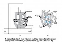
Two pictures are attached to assist in the discussion. I may not explain things very well, but it isn’t the most intuitive subject matter, and I graduated from college eons ago (and forgot most of it).
The induction disk unit is generalized as consisting of two electromagnets (see stator.jpg). They are referred to as shunt and series magnets, as one of the windings are connected in shunt with the load (voltage coil) and the other as being connected in series with the load (current coil).
The series magnet is wound with heavy gauge wire, having very few turns. It is therefore low impedance, and suitable to be inserted in series with the load and not placing undue burden on the circuit. With magnetic circuits, the flux in the core of the electromagnet is in phase with and proportional to the current (and number of turns). So the series magnet generates flux in phase with load current. Turns are very low, sometimes only one turn depending on design.
The shunt magnet is wound with many turns of very small gauge wire. It exhibits a very high impedance, which is predominantly inductive in nature. The high impedance is suitable for insertion in parallel with the load, hence is the load voltage measuring element. It does not consume significant power, which would affect accuracy. In an inductive circuit current lags voltage by 90 degrees, so the load voltage causes a very small current to flow which is lagging by 90 degrees. Even though the current magnitude is small, the numerous turns aid to produce a significant flux which is proportional again to current and in phase. So the shunt magnet generates flux 90 degrees lagging load voltage.
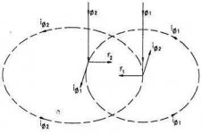
An aluminum disc on a shaft is inserted into the magnetic flux airgap. Then the crazy magic begins (see Eddy.jpg). The fluxes produced by each of the series and shunt magnets induce eddy currents (little circulating currents) in the disc. These eddy currents produce their own fluxes, which interact with the original fluxes to produce mechanical torque on the disk. The torque impressed on the disc is proportional to the magnetic flux magnitudes and also to the sine of the angle between them. So if voltage and current are in phase (100% of VA is watts), then the two electromagnet fluxes are 90 degrees out of phase (the voltage coil has shifted its flux by 90). If the two fluxes are 90 degrees out of phase, then the sine relationship shows torque will be at a maximum. Conversely, if voltage and current are 90 degrees apart, fluxes will be in phase, and torque will be zero. This interaction of fluxes in the induction disk is what gives the stator torque proportional to watts.
However, we really don’t want only torque proportional to watts, we want speed proportional to watts.
Therefore, a permanent magnet is installed around the disc to set up a constant and opposing force which is proportional to the speed of the disk. Zero disk movement results in zero force on the disk from the PM, as no eddy currents are produced. A fast disk rotation results in greater opposing (retarding) force, as greater eddy currents are generated. This keeps the disk from “running away” in speed, and results in speed being proportional to input watts. Without the PM loading the circuit, a constant input of torque from the series/shunt magnet interaction would result in the disk running at constant acceleration, with eventual infinite speed.
With a disk moving with speed proportional to watts, we can now perform mathematical integration by counting the number of rotations of this disk, and turning a mechanical register with gearing. Each turn now becomes a scalar measurement of energy measured in watt-hours. Oh yeah, it also is directionally sensitive, so power flow in the reverse direction will cause the disk to rotate the opposite direction. Some meters are ratcheted to prevent this, others are permitted to depending on the application and Power Purchase Agreement.
The total device is termed a stator, which is kind of like a two-phase AC motor that rotates according to input energy. If I have a three phase system, I can easily implement a complete three phase watthour meter by connecting three stators on the same shaft. Each stator contributes its own torque to the shaft, with a single shaft accumulating total three phase energy.
An amazing little device.
The induction disk unit is generalized as consisting of two electromagnets (see stator.jpg). They are referred to as shunt and series magnets, as one of the windings are connected in shunt with the load (voltage coil) and the other as being connected in series with the load (current coil).
The series magnet is wound with heavy gauge wire, having very few turns. It is therefore low impedance, and suitable to be inserted in series with the load and not placing undue burden on the circuit. With magnetic circuits, the flux in the core of the electromagnet is in phase with and proportional to the current (and number of turns). So the series magnet generates flux in phase with load current. Turns are very low, sometimes only one turn depending on design.
The shunt magnet is wound with many turns of very small gauge wire. It exhibits a very high impedance, which is predominantly inductive in nature. The high impedance is suitable for insertion in parallel with the load, hence is the load voltage measuring element. It does not consume significant power, which would affect accuracy. In an inductive circuit current lags voltage by 90 degrees, so the load voltage causes a very small current to flow which is lagging by 90 degrees. Even though the current magnitude is small, the numerous turns aid to produce a significant flux which is proportional again to current and in phase. So the shunt magnet generates flux 90 degrees lagging load voltage.
An aluminum disc on a shaft is inserted into the magnetic flux airgap. Then the crazy magic begins (see Eddy.jpg). The fluxes produced by each of the series and shunt magnets induce eddy currents (little circulating currents) in the disc. These eddy currents produce their own fluxes, which interact with the original fluxes to produce mechanical torque on the disk. The torque impressed on the disc is proportional to the magnetic flux magnitudes and also to the sine of the angle between them. So if voltage and current are in phase (100% of VA is watts), then the two electromagnet fluxes are 90 degrees out of phase (the voltage coil has shifted its flux by 90). If the two fluxes are 90 degrees out of phase, then the sine relationship shows torque will be at a maximum. Conversely, if voltage and current are 90 degrees apart, fluxes will be in phase, and torque will be zero. This interaction of fluxes in the induction disk is what gives the stator torque proportional to watts.
However, we really don’t want only torque proportional to watts, we want speed proportional to watts.
Therefore, a permanent magnet is installed around the disc to set up a constant and opposing force which is proportional to the speed of the disk. Zero disk movement results in zero force on the disk from the PM, as no eddy currents are produced. A fast disk rotation results in greater opposing (retarding) force, as greater eddy currents are generated. This keeps the disk from “running away” in speed, and results in speed being proportional to input watts. Without the PM loading the circuit, a constant input of torque from the series/shunt magnet interaction would result in the disk running at constant acceleration, with eventual infinite speed.
With a disk moving with speed proportional to watts, we can now perform mathematical integration by counting the number of rotations of this disk, and turning a mechanical register with gearing. Each turn now becomes a scalar measurement of energy measured in watt-hours. Oh yeah, it also is directionally sensitive, so power flow in the reverse direction will cause the disk to rotate the opposite direction. Some meters are ratcheted to prevent this, others are permitted to depending on the application and Power Purchase Agreement.
The total device is termed a stator, which is kind of like a two-phase AC motor that rotates according to input energy. If I have a three phase system, I can easily implement a complete three phase watthour meter by connecting three stators on the same shaft. Each stator contributes its own torque to the shaft, with a single shaft accumulating total three phase energy.
An amazing little device.
Attachments
Very perceptive. We truly do stand on the shoulders of giants, at least in the electrical industry (the only one I am able to claim competence in).
In fact, the first numeric (microprocessor) controlled relays had very limited computational abilities. Calculating a sine or cosine function was extremely processor intensive (I think they were using Taylor or Maclaurin's series), and made it impossible to sample and calculate every 1/4 power system cycle. So how does one implement a distance relay (phase angle sensitive) numerically when you can't calculate trig functions?
They implemented the calculation of positive or negative torques by "stealing" the physical methods used by the electromechanical relay pioneers of the 1920's and 30's. Induction disk is a cosine function, induction cup is sine. Use phase comparators to implement: real component is a cosine comparator, imaginary component is a sine comparator. Would take me a few days to look up the method, but really quite ingenious. Going back to the basics, and you can't cheat by implementing a trig equation in code.
I think, don't hold me to it, that cpus, at least mid-90s, looked up trig values in a table then interpolated. Very slow even when compared to other slow ops like division.
OTOH, I really enjoyed learning how very basic analog circuits could integrate/differentiate and let you Calc speed, position, etc.
OTOH, I really enjoyed learning how very basic analog circuits could integrate/differentiate and let you Calc speed, position, etc.
- Status
- This old topic is closed. If you want to reopen this topic, contact a moderator using the "Report Post" button.
- Home
- General Interest
- Everything Else
- Power factor, watts, and VI - I think I get it