Hi there gentlemen / gentleladies,
I have the below radio that currently has to get recharged for 3 hours before it can play music for 8. It doesn't play while plugged in, I was hoping you geniuses can guide me on how it would be possible to adapt some new wiring to allow me to remove the battery and solely apply a 5V USB Wall adapter or 5VAC straight to the radio. Again below is the link. I was told that the below item from Ebay via cutting the wires and rewiring will help. Not sure if I rewire to the current battery cables once I unplugged them from the radio. Right now the radio recharges via a USB cable. The radio is rated 5V
AC 110V 220V Wall Adapter Power Supply DC 5V 1A 1000mA for Roku HD Box | eBay
Attachments
Mooley, I'm a total Noob, but regarding the polarity, wouldnt the red be positive and the black be negative. If I cut up an USB doesnt it have 4 wires, Red, black and the other two colored ones are for data. If I just use red and black and match it up I should be good right?
Red should be positive but I would never ever assume. Measure it on a voltmeter and be sure. For the USB, the outer pins are the 5 volt supply, again I would measure the voltage first and confirm which is positive and which is negative before connecting it up.
Mooley, can you recommend a voltmeter from Amazon? They look like PKE Meters from the Ghost Buster movie to me.
If you only want a meter for this one project then a cheapo one is all you need,
http://www.amazon.com/Professional-...TF8&qid=1411578426&sr=8-1&keywords=multimeter
If you think you might be interested in more advanced projects and would use a meter more then you need something much better and tougher, probably in the $50 to $100 range (I'm guessing your in the US).
It all depends want you want it to do. And you might pick up a cheap meter at some "cheap shops" or automotive stores. I've even seen them in supermarkets.
No Diodes at all, I mean I'm totally new to all of this. I can get some from RadioShack. What will I do with these?
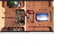
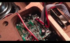
Here I have another thought as well. There's a module connected right now that feeds to the current amp that utilizes an Aux In and the USB side to recharge the battery. I was thinking is it possible to isolate the 6 wires from the board which is connected via a pin and identify what does what? I want to keep the Aux In wires to do what they do, but I was thinking of removing the power ones and redirecting this to the current red/black ones that are attached to the battery. Is this possible? See pic below. to the upper left is the Aux/USB module.
Here I have another thought as well. There's a module connected right now that feeds to the current amp that utilizes an Aux In and the USB side to recharge the battery. I was thinking is it possible to isolate the 6 wires from the board which is connected via a pin and identify what does what? I want to keep the Aux In wires to do what they do, but I was thinking of removing the power ones and redirecting this to the current red/black ones that are attached to the battery. Is this possible? See pic below. to the upper left is the Aux/USB module.
Attachments
If you only want a meter for this one project then a cheapo one is all you need,
Amazon.com: AC/DC Professional LCD Digital Voltmeter Multimeter Tester Checker: Automotive
If you think you might be interested in more advanced projects and would use a meter more then you need something much better and tougher, probably in the $50 to $100 range (I'm guessing your in the US).
It all depends want you want it to do. And you might pick up a cheap meter at some "cheap shops" or automotive stores. I've even seen them in supermarkets.
yea a cheapo one for now is good. This is only to adapt bluetooth to my fathers old radio that I'm handing down to my son. so I'm taking apart another system that some engineers already did their RandD on and just needed some feedback on the power side. I'am in the US. Mooley thanks a million.
I can draw it for you if you want to do it. If you cut the red wire from the battery and connect the diode in series with that red wire then if red is positive the diode will be positioned with its "striped" end toward the radio and the radio will still work.
If you then connect the USB supply in place of the battery (still keeping the diode in the lead), then if you have the polarity correct the radio will work. If you have it wrong, the diode will block the current flow and stop any damage.
You still need to be sure the battery is a 4.8 volt type though (4 cells), or whether it is some other voltage such as a 3.6 volt lithium ion battery.
Identifying all the leads on that plug is one of those things where you need to be sat in front of it really.
Its a bit difficult to just visualise what you mean tbh. If the radio is fully functional on battery then I would think its just a case of making sure the USB input supply takes the place of the battery, possibly also disconnecting the supply from its normal route onto the PCB. If that makes sense...
Back in a little while.
Identifying all the leads on that plug is one of those things where you need to be sat in front of it really.
Its a bit difficult to just visualise what you mean tbh. If the radio is fully functional on battery then I would think its just a case of making sure the USB input supply takes the place of the battery, possibly also disconnecting the supply from its normal route onto the PCB. If that makes sense...
Back in a little while.
Ok, will do. Lots of traction so far thanks to you. Diodes ordered-check, voltmeter ordered-check. I'll separate each of the 6 wires from the USB/Aux In Module and try to identify which one does what.
I bought 100 Diodes, are they reusable or one time only? Secondly, I'm assuming the Positive wire will read a voltage which I'll let you know what that is, but does the negative wire not produce a voltage or is it much much lower than the red/+?
You only need one diode ")
With the polarity, if the red meter lead is on the more positive point (hopefully the red lead) then the meter would show say 5.12 volts. If the reading were -5.12 then you would know that the red meter lead wasn't on the most positive point.
Remember voltages are always relative one point to another. It would be just as valid to say the black wire is at minus 5 volts with respect to the red for example.
Mooly, quick question. Right now I've been using 24 gauge speaker wire for testing out my speakers connected to a 5v amp. That was easy doing the connections. But as this project is maturing now, I was wondering if I'm using the right wire for my application and also which wires are best for electrical wiring that involves power. Is the same speaker wire ok? I doubt it right!
This is the speaker wire I'm using at the moment;
http://www.radioshack.com/product/index.jsp?productId=2102499
This is the speaker wire I'm using at the moment;
http://www.radioshack.com/product/index.jsp?productId=2102499
Last edited:
I would have thought 24 gauge (A.W.G.) should be good for around 3 amps for general wiring duty. So yes, it should be fine... just remember that speaker wire probably has definite limits on insulation resistance meaning its not suitable for mains voltage even if it can handle the current.
Legth of cale run plays a part too. If you were carrying 3 amps over a 100ft or more then you would want a heavier cable. Over a few inches in a chassis and there is no problem.
A 5 volt USB powered amp is way down the list when it comes to power delivery
Legth of cale run plays a part too. If you were carrying 3 amps over a 100ft or more then you would want a heavier cable. Over a few inches in a chassis and there is no problem.
A 5 volt USB powered amp is way down the list when it comes to power delivery
- Status
- This old topic is closed. If you want to reopen this topic, contact a moderator using the "Report Post" button.
- Home
- General Interest
- Everything Else
- Convert Rechargeable Battery Radio to AC/USB Wall Powered