This is a thread in which I intend to describe some tests/measurements on speaker cables (‘speaker line’) that I am planning to do for to study the effects speaker line/speaker load combination may have on the driving amplifier.
This, after being intrigued by jneutron relevant posts at JC thread and a few things mentioned by Cyril Bateman in this article: https://community.klipsch.com/index.php?app=core&module=attach§ion=attach&attach_id=86522
There are some different ways that measurements can be performed, I will try a few of them which are compatible with the instruments I have.
What I will achieve and how, is to be seen. I don’t mind much on the outcome though, as it is the process of testing that I enjoy!
Testing is time consuming. Recording and documenting is even more but it is important to keep track of the process.
The flow of uploading will be accordingly slow.
I welcome comments, criticism and bushing on wrong/inappropriate methods and implementation mistakes but most of all on false assumptions and wrong conclusions. This is the benefit of posting here. Communication and what comes through it.
I choose to start by describing the bits and pieces that will be used in the tests, then the equipment, and the jigs. What I will use is not state of the art, the testing set-ups are easily replica-able by many here if they want to.
The flow will continue with the choice of DUTs, the testing methods and finally the tests themselves.
Welcome on board.
George
Attachments
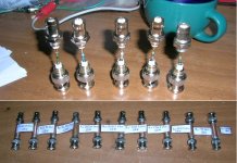
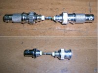
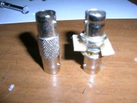
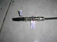
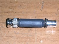
Rs construction
Rs construction.
Rs, stands for Rseries.
It is simply a resistor to be placed in series within a measuring jig.
I made it in a way that retains -as much as possible for my amateur needs- the coaxial construction form and properties of cabling based on BNC connectors .
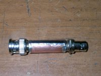
The resistive element is soldered between the center pins of the two BNC connectors. A cylindrical copper foil is soldered -coaxially to the resistor- around the outer shield side of the two BNC connectors.
If the BNC connectors are silvered, copper foil can be soldered around them with no BNC surface preparation.
For the chromed BNC connectors, before soldering the copper foil on it, I lightly file the chrome film, exposing the copper metalization underneath.
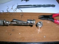
I cut the copper foil to size, clean the surface with fine grit paper and pre-form it into a cylinder by wrapping it around a 8mm diameter drill bit.
I solder the resistor at the inner pins using a small 16 Watt soldering iron.
For soldering the copper foil around the BNC connectors I use 100 Watt soldering iron.
Due to a lot of metal mass involved, the heating amount and heating time required, will make the plastic BNC inserts soften, causing inner pin misalignment.
For to prevent this, I plug BNC adaptors on both BNC connectors before soldering. These adaptors hold the inner pins in place during soldering and cooling phases and provide added metal mass (the latter is an extra burden during soldering but good during cooling).
Adaptors have to be just plugged-in to the BNC connectors but not all-in and locked, else soldering heat will make adaptor’s plastic inserts to stick with the BNC connectors.
Soldering time is a critical parameter set by trial and error. I had a few failed Rs constructions and a lot of stuck adaptors during the process of building all the coaxial Rs units.
During soldering the edges of the copper cylinder to the BNC metal, the copper foil is held in place by wrapping around it a few turns of enameled wire. Enamel prevents soldering of the wire to the copper foil. Wire is removed after temperature has dropped sufficiently (*).
George
(*) My finger tips are burn hardened.
I prevent burn blisters formation by re-heating burned skin area over the flame of a cigarette lighter, immediately after the accidental hot metal touch.
I bear the pain from the flame burn for some 5 seconds, which is enough for a “cure”. This sounds as a rude and counterintuitive action but is very effective (trick used by metal welders, they know).
If you experience a hand burn but you don’t fancy doing it, drip your hand into a bowl with salted water and hold them there for a while. This doesn’t work for me but at least this method bears some scientific justification.
George
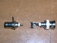
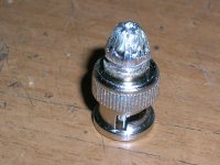
Rs construction.
Rs, stands for Rseries.
It is simply a resistor to be placed in series within a measuring jig.
I made it in a way that retains -as much as possible for my amateur needs- the coaxial construction form and properties of cabling based on BNC connectors .
The resistive element is soldered between the center pins of the two BNC connectors. A cylindrical copper foil is soldered -coaxially to the resistor- around the outer shield side of the two BNC connectors.
If the BNC connectors are silvered, copper foil can be soldered around them with no BNC surface preparation.
For the chromed BNC connectors, before soldering the copper foil on it, I lightly file the chrome film, exposing the copper metalization underneath.
I cut the copper foil to size, clean the surface with fine grit paper and pre-form it into a cylinder by wrapping it around a 8mm diameter drill bit.
I solder the resistor at the inner pins using a small 16 Watt soldering iron.
For soldering the copper foil around the BNC connectors I use 100 Watt soldering iron.
Due to a lot of metal mass involved, the heating amount and heating time required, will make the plastic BNC inserts soften, causing inner pin misalignment.
For to prevent this, I plug BNC adaptors on both BNC connectors before soldering. These adaptors hold the inner pins in place during soldering and cooling phases and provide added metal mass (the latter is an extra burden during soldering but good during cooling).
Adaptors have to be just plugged-in to the BNC connectors but not all-in and locked, else soldering heat will make adaptor’s plastic inserts to stick with the BNC connectors.
Soldering time is a critical parameter set by trial and error. I had a few failed Rs constructions and a lot of stuck adaptors during the process of building all the coaxial Rs units.
During soldering the edges of the copper cylinder to the BNC metal, the copper foil is held in place by wrapping around it a few turns of enameled wire. Enamel prevents soldering of the wire to the copper foil. Wire is removed after temperature has dropped sufficiently (*).
George
(*) My finger tips are burn hardened.
I prevent burn blisters formation by re-heating burned skin area over the flame of a cigarette lighter, immediately after the accidental hot metal touch.
I bear the pain from the flame burn for some 5 seconds, which is enough for a “cure”. This sounds as a rude and counterintuitive action but is very effective (trick used by metal welders, they know).
If you experience a hand burn but you don’t fancy doing it, drip your hand into a bowl with salted water and hold them there for a while. This doesn’t work for me but at least this method bears some scientific justification.
George
Attachments

Rg construction
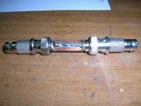
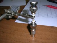
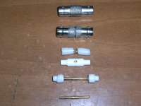
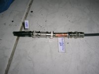
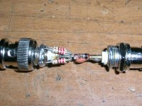
Rg construction.
Rg stands for Rground.
It is a resistor to be placed in series with the ground-side conductor within a measuring jig for the purpose of measuring the voltage drop across it, so that the current of a grounded circuit can be measured or ‘viewed’. Thus another abbreviation used for such a resistor is ‘cvr’, which stands for current viewing resistor.
Again, it is made in a way that retains the coaxial construction form and properties of cabling based on BNC connectors.
It is the inside-out and outside-in concept of my Rs build.
With Rg, the center pins of the two BNC connectors are joined by a straight metal connection, while the resistive element is formed by an even number of resistors, arranged coaxially around the center conductor.
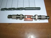
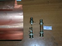
The two ends of these resistors can be soldered on two copper tube sections, or around the perimeter of a male to male BNC adaptor which has a cross cut in the middle, splitting it into two cylinders. This is the approach I adopted, which was inspired from jneutron’s copper tube concept: http://www.diyaudio.com/forums/atta...-diodes-generic-power-supply-loadresistor.jpg
Cutting the BNC adaptor with metal hand saw is easy. Before cutting in two a chromed adapter, I lightly filed it down to the copper layer for to ease the resistors soldering. With silvered BNC adaptor, surface filing is not applicable.
The difficult part starts after cutting the metal skirt of the adaptor.
For start, there are many variations of plastic inserts and center conductors. All are manageable, each requiring a different handling approach. I prefer the variation with the one-piece cylindrical center pin.
Before soldering the resistors, I remove the inner parts (plastic spacers and inner pin) of the adaptor. I do this by lightly heating the adaptor’s barrel with a cigarette lighter for ~ 3 seconds. Then I pull the two barrels apart and the inner parts get out from the one of the barrels. The other barrel is emptied too by side stretching the inner spacer with a small flat screwdriver so it gets unstuck after ~ half a minute of manipulation.
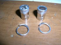
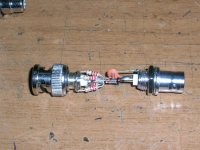
Around each half of the now empty adaptor, using the 100W soldering iron, I solder a ring made of solid core wire. The wire rings are soldered at the end of the knurled section, not further away.
Wire ring is the platform over which the ends of the resistors will be soldered . It serves two functions:
1. It provides for a raised surface, so that the resistor ends don’t have to be bent down for to reach the adaptor’s barrel, easing the proper positioning of the resistors during soldering.
2. 2. As the soldering of the resistors has to be done after repositioning the inner parts, this ring provides for a thermal decoupling btn the resistor ends and the adaptor’s barrel metal mass, so that the soldering can be done with the small 16W iron, without excessively heating and deforming the plastic spacers.
After the wire rings are soldered in place, the inner parts are repositioned in their place. Correct repositioning ends with the two barrels spaced ~ 1.5mm apart, the width of the hand saw used to cut the barrel in two, the construction having the same total axial length as the original uncut adaptor.
Then, the resistors are soldered over the wire rings, equally spaced around the periphery.
I use ten resistors, each having 10x the resistance of the intended Rg Ohmic value.
Although the resistor soldering is done with the low power iron, still the heat may deform the inner spacers, necessitating the same precautionary measures as with Rs copper foil soldering ( attaching the same adaptors on each side for proper center pin alignment).
George
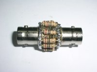
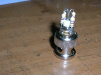
Rg construction.
Rg stands for Rground.
It is a resistor to be placed in series with the ground-side conductor within a measuring jig for the purpose of measuring the voltage drop across it, so that the current of a grounded circuit can be measured or ‘viewed’. Thus another abbreviation used for such a resistor is ‘cvr’, which stands for current viewing resistor.
Again, it is made in a way that retains the coaxial construction form and properties of cabling based on BNC connectors.
It is the inside-out and outside-in concept of my Rs build.
With Rg, the center pins of the two BNC connectors are joined by a straight metal connection, while the resistive element is formed by an even number of resistors, arranged coaxially around the center conductor.
The two ends of these resistors can be soldered on two copper tube sections, or around the perimeter of a male to male BNC adaptor which has a cross cut in the middle, splitting it into two cylinders. This is the approach I adopted, which was inspired from jneutron’s copper tube concept: http://www.diyaudio.com/forums/atta...-diodes-generic-power-supply-loadresistor.jpg
Cutting the BNC adaptor with metal hand saw is easy. Before cutting in two a chromed adapter, I lightly filed it down to the copper layer for to ease the resistors soldering. With silvered BNC adaptor, surface filing is not applicable.
The difficult part starts after cutting the metal skirt of the adaptor.
For start, there are many variations of plastic inserts and center conductors. All are manageable, each requiring a different handling approach. I prefer the variation with the one-piece cylindrical center pin.
Before soldering the resistors, I remove the inner parts (plastic spacers and inner pin) of the adaptor. I do this by lightly heating the adaptor’s barrel with a cigarette lighter for ~ 3 seconds. Then I pull the two barrels apart and the inner parts get out from the one of the barrels. The other barrel is emptied too by side stretching the inner spacer with a small flat screwdriver so it gets unstuck after ~ half a minute of manipulation.
Around each half of the now empty adaptor, using the 100W soldering iron, I solder a ring made of solid core wire. The wire rings are soldered at the end of the knurled section, not further away.
Wire ring is the platform over which the ends of the resistors will be soldered . It serves two functions:
1. It provides for a raised surface, so that the resistor ends don’t have to be bent down for to reach the adaptor’s barrel, easing the proper positioning of the resistors during soldering.
2. 2. As the soldering of the resistors has to be done after repositioning the inner parts, this ring provides for a thermal decoupling btn the resistor ends and the adaptor’s barrel metal mass, so that the soldering can be done with the small 16W iron, without excessively heating and deforming the plastic spacers.
After the wire rings are soldered in place, the inner parts are repositioned in their place. Correct repositioning ends with the two barrels spaced ~ 1.5mm apart, the width of the hand saw used to cut the barrel in two, the construction having the same total axial length as the original uncut adaptor.
Then, the resistors are soldered over the wire rings, equally spaced around the periphery.
I use ten resistors, each having 10x the resistance of the intended Rg Ohmic value.
Although the resistor soldering is done with the low power iron, still the heat may deform the inner spacers, necessitating the same precautionary measures as with Rs copper foil soldering ( attaching the same adaptors on each side for proper center pin alignment).
George
Attachments
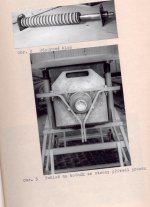
Great job, George!!
I like these coaxial shunts. You know, in the eighties I worked for a Research Institute at High power testing and certifying lab. We worked on fast high current shunts and HV dividers. There is a lot in common, though the dimensions are very different.
Looking forward your results!!
Cheers,
Pavel
I like these coaxial shunts. You know, in the eighties I worked for a Research Institute at High power testing and certifying lab. We worked on fast high current shunts and HV dividers. There is a lot in common, though the dimensions are very different.
Looking forward your results!!
Cheers,
Pavel
Attachments
Rt construction
Thank you Pavel!
When I start measuring and fail, I hope to set me straight")
I understand that increasing the power and/or the rising rate of the signal will show the slightest assymetry of the construction.
The precision of construction for such resistors intended for serious work in calibration labs is enormous.
I can’t do that (and I wouldn’t have to do that, since to start with, my measuring apparatus is uncalibrated)
In these -to be performed- tests I will not go past 1W.
The last upload of the day:
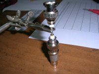
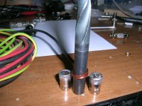
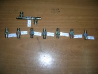
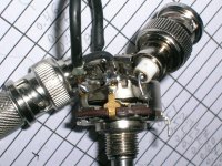
Rt construction.
Rt stands for Rtermination.
It is a resistor to be placed at the end of a cable line for to provide a load across the two conductors of the line or to ‘terminate’ the line with a defined ‘termination load’
This one too is made in a way that retains the coaxial construction form and properties of cabling based on BNC connectors.
It is the easiest to fabricate, compared to Rs or Rg.
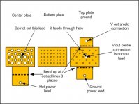
A BNC connector, on which a number of resistors btn center pin and shield side are soldered axi-symmetrically.
For a n number of resistors, each resistor shall have n x the resistance of the intended Rt Ohmic value.
Instead of building many different valued Rt, a potentiometer can be connected between center pin and shield side of a BNC connector. This will work well at low frequencies but not at RF due to the asymmetry of the construction.
A BNC connector with a short btn center pin and shield side is a 0 Ohm Rt or simply a ‘Short’.
Connecting a ‘Short’ at one end of an Rs or an Rg, turns them into an Rt, therefore I didn’t have to build many different Rt as I have already many of Rs and Rg.
George
Thank you Pavel!
When I start measuring and fail, I hope to set me straight
I understand that increasing the power and/or the rising rate of the signal will show the slightest assymetry of the construction.
The precision of construction for such resistors intended for serious work in calibration labs is enormous.
I can’t do that (and I wouldn’t have to do that, since to start with, my measuring apparatus is uncalibrated)
In these -to be performed- tests I will not go past 1W.
The last upload of the day:
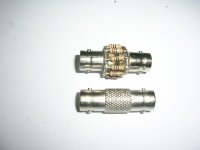
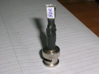
Rt construction.
Rt stands for Rtermination.
It is a resistor to be placed at the end of a cable line for to provide a load across the two conductors of the line or to ‘terminate’ the line with a defined ‘termination load’
This one too is made in a way that retains the coaxial construction form and properties of cabling based on BNC connectors.
It is the easiest to fabricate, compared to Rs or Rg.
A BNC connector, on which a number of resistors btn center pin and shield side are soldered axi-symmetrically.
For a n number of resistors, each resistor shall have n x the resistance of the intended Rt Ohmic value.
Instead of building many different valued Rt, a potentiometer can be connected between center pin and shield side of a BNC connector. This will work well at low frequencies but not at RF due to the asymmetry of the construction.
A BNC connector with a short btn center pin and shield side is a 0 Ohm Rt or simply a ‘Short’.
Connecting a ‘Short’ at one end of an Rs or an Rg, turns them into an Rt, therefore I didn’t have to build many different Rt as I have already many of Rs and Rg.
George
Attachments
Last edited:
I found this book.
Coaxial Electrical Circuits for Interference-Free Measurements - The IET
The more pages I read, the more I understand the impact of construction and set-up details on the measurement output.
Just on time!
George
Coaxial Electrical Circuits for Interference-Free Measurements - The IET
The more pages I read, the more I understand the impact of construction and set-up details on the measurement output.
Just on time!
George
Thank you John!
Sorry for not responding earlier.
I am trying to tame some “metrological” issues (I see Pavel smiling ).
Also I make space on my bench by clearing some dead bodies (amps for repair).
If all goes well, in two-three days I will post some data to keep the interest alive
George
Sorry for not responding earlier.
I am trying to tame some “metrological” issues (I see Pavel smiling
).Also I make space on my bench by clearing some dead bodies (amps for repair).
If all goes well, in two-three days I will post some data to keep the interest alive
George
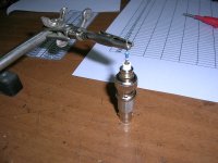
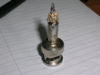
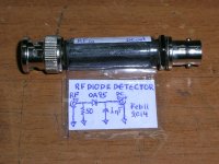
The latest coaxial construction. An RF detector (RF peak to DC converter)
http://epic.mcmaster.ca/~elmer101/sqlaw/sqlaw.html
http://epic.mcmaster.ca/~elmer101/sqlaw/sqlplots.html
http://epic.mcmaster.ca/~elmer101/rfpower/rfpower.html
http://www.hparchive.com/seminar_notes/Pratt_Diode_detectors.pdf
George
http://epic.mcmaster.ca/~elmer101/sqlaw/sqlaw.html
http://epic.mcmaster.ca/~elmer101/sqlaw/sqlplots.html
http://epic.mcmaster.ca/~elmer101/rfpower/rfpower.html
http://www.hparchive.com/seminar_notes/Pratt_Diode_detectors.pdf
George
Attachments
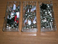
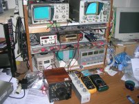
Instruments-Standarts
All my instruments and standards are neither controlled or calibrated.
I only can verify conformance to manuf specs by inter comparison within equipment common operating ranges.
Therefore, although in some post I am referring to amplitude‘measurements’, these are of some value only for comparing between two or more testing set-up results.
-20MHz analog scope HAMEG HM203-7
-100MHz analog scope HP1740A
-Up to 2MHz analog function generator HAMEG HM8030
-Bench (true rms) multimeter KEITHLEY K-175
-Three hand held digital multimeters, two handheld digital LC meters.
-General Radio GR 1434-N Decade Resistor box
-General Radio GR 107-M Variable Inductor.
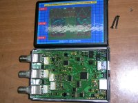
- DDGS2A multi function USB unit. It is built around the DDS IC AD9954. It is clocked at 400MS/s from a 20MHz crystal. It goes up to 200MHz but the alias-free range is up to 150-160MHz. It works as: Digital function generator and (independent or synchronized) 2Ch scope, Envelope Detector, FFT, Freq counter.
George
All my instruments and standards are neither controlled or calibrated.
I only can verify conformance to manuf specs by inter comparison within equipment common operating ranges.
Therefore, although in some post I am referring to amplitude‘measurements’, these are of some value only for comparing between two or more testing set-up results.
-20MHz analog scope HAMEG HM203-7
-100MHz analog scope HP1740A
-Up to 2MHz analog function generator HAMEG HM8030
-Bench (true rms) multimeter KEITHLEY K-175
-Three hand held digital multimeters, two handheld digital LC meters.
-General Radio GR 1434-N Decade Resistor box
-General Radio GR 107-M Variable Inductor.
- DDGS2A multi function USB unit. It is built around the DDS IC AD9954. It is clocked at 400MS/s from a 20MHz crystal. It goes up to 200MHz but the alias-free range is up to 150-160MHz. It works as: Digital function generator and (independent or synchronized) 2Ch scope, Envelope Detector, FFT, Freq counter.
George
Attachments
Last edited:
All my instruments and standards are neither controlled or calibrated.
I only can verify conformance to manuf specs by inter comparison within equipment common operating ranges.
Therefore, although in some post I am referring to amplitude‘measurements’, these are of some value only for comparing between two or more testing set-up results. George
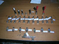
Nice. Your methodology seems very rigorous.
Every so often, a tech will have used an instrument which is out of date. In such cases, we will do what we call an "abridged calibration". A dvm for example, I will connect it to a source consistent with the range it was used for, and two additional fully calibrated units at the exact same time. the last dmm I did this with was consistent in reading to the cal'd units, all three read to .0001 volt accuracy in the 10 volt range. This was the LSB.
btw, picked up a mess of .093" brass plate yesterday, already drew up the metals.
jn
Attachments
we will do what we call an "abridged calibration
Yes John
One calibrated instrument is a must. It can be utilized as a kind of ‘local transfer standard’.
I don’t have this ‘one instrument’. So I use a technique I call ‘potentially statistical dictatorship’
:Say 3 instruments take a reading from a single source. The instrument that deviates the most gets the bad name.
Any number of participating instruments from 5 and above (Student Table) tends to make the results of this technique more trusty.
But there are some points that need to be addressed!!!
In fact this how I started to think over your posts on cables.
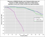
I was comparing the freq response of three scopes connected simultaneously to a signal source.
I lost my mind with the abnormal and abrupt deviation between the three when I entered the HF area.
It was due to standing wave resonance at the three interconnecting cables.
Standard input –output termination and individual connection of each scope to the source cleared the issue.
btw, picked up a mess of .093" brass plate yesterday, already drew up the metals.
OMG! I love cheese with holes. Is it salty and pepered?
George
Attachments
- Status
- This old topic is closed. If you want to reopen this topic, contact a moderator using the "Report Post" button.
- Home
- General Interest
- Everything Else
- Jneutron influence΄ consequences: