Audacity has no difficulty in resolving HD of 1kHz signal.
What is design role of this amplification stage?
What is input signal from previous stage? How is this loaded by input of 5532 v TLE2072?
How are outputs loaded? Output impedance of these two chips appears to be quite different.
I time aligned OMNICRON/Pi to put this out of my mind, and just listened. ABX confirmed ability to hear difference. I didn't make subjective choice before results revealed.
Distortion spec for TLE2072 is certainly nothing special, but likely much better than distortion of recording chain. How this rolls into "sound" or "sound quality" loops into seeming endless topic, regardless of recording/playback chain.
For most, pure 2nd harmonic -36dB is somewhat above threshold of audibility with single tone stimulus. But being so far above TLE2072 spec strongly suggests poor plug and play implementation in swapping out 5532.
Thanks for your efforts, look forward to your next adventure.
Poor "plug and play" sums this one up brilliantly. Given that many like the sound of equipment that lets say "emphasises" certain distortions I thought this would make an interesting test. Those with "cold sounding" amps might have warmed to the distortion added by the TLE2072. The stage is just the typical opamp output circuit in many a CD player, this one hampered by 5 volt rails although in stock form there doesn't seem to be a problem.
Unfortunately there were not enough participants in this test... oh well")
Unfortunately there were not enough participants in this test... oh well
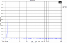
Audacity has no difficulty in resolving HD of 1kHz signal.
Low resolution/dynamic range in both amplitude and bin width. You can see it in Mooly's images.
Those with "cold sounding" amps might have warmed to the distortion added by the TLE2072.
Karl, this is completely wrong track. Compare NE5532 with OPA627. There will be no excuse to distortion in case of OPA627. "Cold" or "warmer" sound has nothing in common with harmonic distortion as low as is in case of opamps.
Low resolution/dynamic range in both amplitude and bin width. You can see it in Mooly's images.
In case of 1kHz, and Audacity's 16k FFT limit, bin width is more than sufficient for resolving distortion limits of TLE2072 spec, and virtually any loudspeaker played at any level.
In case of 1kHz, and Audacity's 16k FFT limit, bin width is more than sufficient for resolving distortion limits of TLE2072 spec, and virtually any loudspeaker played at any level.
Sorry, sounds like empty phrases to me. Would you show any measurement like this made with Audacity?
Attachments
Pavel,
Many surgeons prefer stone knives.
I'm not advocating Audacity as tool of choice, but it is remarkably powerful, open source, and quite workable.
Here is 1kHz 0dBFS with 3khz -115dB with 1024 bin FFT:

A throwback to when digital tools were scarce, and very expensive. Since 1kHz is known stimulus a notch filter is applied, available as Audacity effect, and result becomes:

The notch filter is narrow and clean enough for resolving 2kHz harmonic too.
Many surgeons prefer stone knives.
I'm not advocating Audacity as tool of choice, but it is remarkably powerful, open source, and quite workable.
Here is 1kHz 0dBFS with 3khz -115dB with 1024 bin FFT:
A throwback to when digital tools were scarce, and very expensive. Since 1kHz is known stimulus a notch filter is applied, available as Audacity effect, and result becomes:
The notch filter is narrow and clean enough for resolving 2kHz harmonic too.
This is an I/V and more importantly filter stage. I haven't simulated it, but my guess would be that it might be a little hard on the opamp's output stage. Which could explain why the much beefier 5532 did just fine while the TLE2072 (with load immunity being about a factor of 4 worse) struggled. Filter circuits may also exhibit higher internal levels. I guess I'll just sim the thing tomorrow.
This is an I/V and more importantly filter stage. I haven't simulated it, but my guess would be that it might be a little hard on the opamp's output stage. Which could explain why the much beefier 5532 did just fine while the TLE2072 (with load immunity being about a factor of 4 worse) struggled. Filter circuits may also exhibit higher internal levels. I guess I'll just sim the thing tomorrow.
Try this. I find that opamp sims aren't always reliable but must admit that here and using a FET opamp... well the result is obvious. The effect on a scope wasn't quite this bad and no tendency to hard clipping. And this is at way below the -/+2.8 volts pk/pk that 0db gives.
Attachments
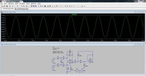
Seems the problem simply is input common-mode range. The TLE2072 is given with +5/-1.9 V typical on a +/-5 V supply, and there's a unity gain buffer in there that has to swing down to -2.83 V, as do its inputs. Which would correlate with distortion setting in a little under the -3 dBFS mark. The NJM5532 typically does +/- 3 V under the same conditions, hence no problems. (Got any mean >0 dBFS test signals like that fs/4, 90° sine? That ought to be it.)
For kicks, one could try a TL072... Inversion time!
Clearly a case of "plug'n'pray". Those are the perils of low supply voltages and non-RRIO opamps.
For kicks, one could try a TL072... Inversion time!
Clearly a case of "plug'n'pray". Those are the perils of low supply voltages and non-RRIO opamps.
- Status
- This old topic is closed. If you want to reopen this topic, contact a moderator using the "Report Post" button.
- Home
- General Interest
- Everything Else
- Purely subjective test. Which do you prefer.