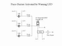
Ok, here's the background. I have three gauges for my car I am installing. These gauges have warning lights, for example, if gas temperatures at the exhaust manifold exceed 1600°F then a warning LED lights. A LED is OK, but I want a loud buzzer to go off when the LED lights. I have designed a circuit for this but I'm not sure if it will work  Any suggestions or comments are greatly appreciated.
Attachments
A few things I forgot to mention, the MOSFET I got from Radio Shack requires 2-4 Volts (positive at the gate) to open the drain-source path. This should not be a problem, as I think the relay has a higher resistance than the MOSFET, and if not I can always throw a resistor in there after the relay. The only thing I need for sure is 9.6 Volts minimum across the relay to get the relay to open up.
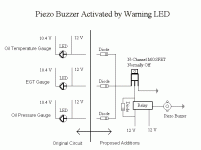
The reason I stuck the diodes in there is because I am afraid of too much current being demanded by other gauges. Only one of the LEDs may be on at any one time. For instance, my oil temperature may be too high but my oil pressure and exhaust gas temperature may be fine, so only one LED out of the three would be on.
The values of 12 and 10.4 Volts were measured with a multimeter, so there's a 1.6 Volt drop across the LED.
Any help is appreciated, even condescending remarks like "you can't use a diode that way dumbass" would be appreciated.
Any just because I like you guys so much you get the dancing banana smiley

Looks too complicated to me !
What are the current requirements of the buzzer ?
(or whats its impedance)
What are the current requirements of the relay ?
(or whats its impedance and minimum voltage)
What current are the LEd's run at when lit ?
(or what is the load resistance to ground ?)
 sreten.
What are the current requirements of the buzzer ?
(or whats its impedance)
What are the current requirements of the relay ?
(or whats its impedance and minimum voltage)
What current are the LEd's run at when lit ?
(or what is the load resistance to ground ?)
Here's a picture of the original circuit with proposed additions. I'm using a MOSFET because I'm afraid anything else might draw too much current from the LED's circuits... I've also added a diode across the relay's coil to prevent voltage spikes from destroying anything.
Edit: Almost forgot. LED current is 8.3 mA. MOSFET impedance is 0.6 ohms. I'm uncertain of relay coil impedance at the moment, but I do have that number at home... Piezo buzzer current requirement is about 80 mA. A npn transistor would probably do the job fine, but component cost isn't much of an object (do I spend $0.79 on one BPT from Radio Shack or $1.95 on one MOSFET from Radio Shack, not much of an issue for a one time thing).
Edit: Almost forgot. LED current is 8.3 mA. MOSFET impedance is 0.6 ohms. I'm uncertain of relay coil impedance at the moment, but I do have that number at home... Piezo buzzer current requirement is about 80 mA. A npn transistor would probably do the job fine, but component cost isn't much of an object (do I spend $0.79 on one BPT from Radio Shack or $1.95 on one MOSFET from Radio Shack, not much of an issue for a one time thing).
Attachments
What we can't see is whether the LED are turned on
by completing the ground connection or the 12V.
I can't see the point of the relay.
If they are turned by completing ground then :
Connect the emitter of a PNP transistor to 12V via a 5R resistor.
Connect the collector via the buzzer to earth.
Connect the base to the points marked 10.4 volts via 3 diodes.
If any LED lights up, the buzzer will sound.
(LED voltage = 1.6 V, diode drop = 0.6V, base-emitter
drop=0.6V, leaving 0.4V across 5R, I = V/R = 80mA.)
If they are turned on by being connected to 12V then
a NPN emitter follower can replace the FET and relay
in your circuit.
 sreten.
by completing the ground connection or the 12V.
I can't see the point of the relay.
If they are turned by completing ground then :
Connect the emitter of a PNP transistor to 12V via a 5R resistor.
Connect the collector via the buzzer to earth.
Connect the base to the points marked 10.4 volts via 3 diodes.
If any LED lights up, the buzzer will sound.
(LED voltage = 1.6 V, diode drop = 0.6V, base-emitter
drop=0.6V, leaving 0.4V across 5R, I = V/R = 80mA.)
If they are turned on by being connected to 12V then
a NPN emitter follower can replace the FET and relay
in your circuit.
li_gangyi said:do you really have to use a relay?? seems like the relay will take more current than just the piezo buzer...and since u are going for a mosfet...might as well drive the buzzer straight...
You're right. I had the relay in there and never questioned myself as to whether or not it was a necessary piece
I'll just drive the buzzer with the MOSFET.
I have to check the LED leads when the LED is off, all of the above voltages were measured when the LEDs were on.
Thanks a lot for the advice guys. I look foward to working on this tonight and getting my car's gauges to work the way I want them to

Ok, I did some more multimetering. If the LED is on (as in the pictures above), the positive side is 12 V and the negative side is 10.4 V. If the LED is off, the positive side is still 12 V but the negative side is 10.8 V. Is there any way to tell from these numbers whether the LED is turned on by completeing the ground or 12 V connection?
If not, how can I tell whether the LED is turned on by completing the 12 V side or completing the ground side?
Thanks again, I think I'm close to getting this to work
If not, how can I tell whether the LED is turned on by completing the 12 V side or completing the ground side?
Thanks again, I think I'm close to getting this to work

sreten said:With the igntion switched off, measure the resistance of the 12V
points to the 12V terminal of the battery. Measure the resistance
of the 10.4V points to earth. Should sort it out.
sreten.
That's what I did this morning, strangely enough before I read this post, checking resistances was the first thing in my head when I woke up this morning
 . The gauges weren't connected to anything, I just checked resistance from positive side to 12V input wire, and negative side to ground wire.
 Even though I'm a total circuit design n00b, I happen to have a DC dual channel 0-30 V 0-3 amp power supply available over the holidays (one of the advantages of working in a lab I guess) that I'm using to test the circuit. I wouldn't want to imagine trying to do this outside in my car, especially with the nasty weather lately :brrr smiley:
Here's what I found, resistance from positive side to 12 V wire is 0 ohms, resistance from negative side to ground is 3.5 Mohms. So, I guess the solution is to use the PNP transistor with resistor on the ground side of the LED.
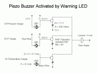
My PNP transistor has a Hfe of 50, and my buzzer requires much less current than I originally thought (only 5mA instead of 80 mA), so there is only going to be 0.1 mA of extra current on the 8.3 mA LED circuit, so I'm fine in that regard.
Thanks for all the help guys, especially sreten, I wouldn't have been able to do it without you, or it would have taken me an extra month
One more question, above sreten suggested connecting the base of a PNP transistor to the 10.4 V negative side of the LED via a diode. Is a diode necessary in this instance? Can the 10.4 V after the LED flow current to the collector side of a PNP transistor? Certainly the diode won't hurt anything, but is it using one more part than I need to? Will I need a diode where the collectors of the three PNP transistors meet before entering the buzzer? I don't think I do but I'm unsure of myself when with anything involving electricity.
Here's the "final" design without diodes, should I add diodes anywhere?
Attachments
I built the circuit pictured above (only one gauge though, not all three hooked together yet), and it didn't work right.
The buzzer is always on (even if the LED is off), however, the buzzer is louder when the LED is on.
If I hook just the resistor -> PNP transistor -> buzzer part of the circuit up to power, the buzzer is completely off. The only thing I can think of is that the negative side of the LED isn't completely off (even though there is a 3.5 million ohm resistance measured there when it is off) and some current is still flowing. I'll have to think about it some more later, but right now I'm stumped...
Ok, I did some simple calulations. Even with a 3.5 MOhm resistance I would still get 0.15 mA of flow through the collector of the PNP transistor, which I guess is enough to be heard... I guess the problem is my Hfe is too high 
I'm kinda stuck on what to do now, but hopefully I'll think of some kind of work around...
As a note, I measured all of the voltages yesterday and they were as the circuit diagram shows.
Edit: I was typing this post an hour ago but forgot to finish it sreten, so I saw your post just after finishing this one. I'll try what you suggests, thanks again.
sreten said:Its probably leakage current.
Tying the bases to 12V with a ~2k resistor should work.
Note that with all 3 on, you'll get 15mA to the buzzer.
I'd go for 3 diodes, 1 transistor, 80R resistor,
tie the base to 12V with a 2k resistor.
sreten.
This makes sense to me, tying the base to 12V will keep the potential at the base high enough to keep the emitter collector path from opening.
What is the purpose of the 3 diodes you suggested adding?
Edit: NM, I can see the diodes usefulness is keeping the other two gauges from flowing current to one if only one gauge is switched on
- Status
- This old topic is closed. If you want to reopen this topic, contact a moderator using the "Report Post" button.
- Home
- General Interest
- Everything Else
- Anyone care to help out a circuit design n00b?


