fdegrove said:Further during the telcon I mentioned the addition of manganese to Cu to promote crystal formation as SE suggested before: guess what?
The reason this is done is to augment the tensile strenght of the Cu wire according to him, NOT more crystals.
Which, BTW, is not what you want in audiowire, the less crystal boundaries the better.
Ag, by its very nature, will tend to form less crystals for a given length of wire than Cu.
Where do you get "Ag" from manganese?
But let's refresh. When I asked if the process you were referring to was their process of adding manganese, you said:
No....You won't even have to add manganese to copper anyway, it contains some in its natural raw state already.
I replied:
But they add more in order to improve crystal formation.
I didn't say anything about growing more crystals.
And what I said was based on the claims made by the inventors of the process in the patent (4,059,437):
It has been found under the present invention that by adding to oxygen-free copper small amounts of manganese in addition to the manganese impurity level present, that the abnormal grain structure can be lessened or eliminated, and that consequently the roughened or "orange peel" surfaces and various forms of cracking and uneven flow during cold forming can be alleviated or eliminated.
Amounts of manganese added at any convenient stage during the production of the oxygen-free copper in the range of approximately 1 to approximately 100 parts per million by weight provide enhanced grain size control during annealing of the copper, a minimum electrical conductivity of 100% I.A.C.S., and increased ductility of the copper as cast or fabricated. Amounts of manganese added in the range of approximately 1 to approximately 50 parts per million by weight provide enhanced grain size control during annealing of the copper, a minimum electrical conductivity of 101% I.A.C.S., and increased ductility of the copper as cast or fabricated. When at least approximately 30 parts per million by weight of manganese are added, ductility is maximized. In each instance, the "orange peel" surfaces and various forms of cracking and uneven flow during cold forming are aleviated or eliminated.
And by the way, this discussion is not about these issues. It's about whether the distortion that John has been measuring is being produced by the wires themselves and has nothing to do with metallurgy and the like. If you want to discuss those issues, let's start a new thread.
se
fdegrove said:Hi,
Maybe not logic per se but the likelyhood for erroneous conclusions is growing as days go by.
Hope this helps,")
Frank, I love to chat with you on this logic thing but this is, as its orginator had hoped, a technical discussion and please do you best NOT to disturb and distract this otherwise very interesting discussion.
If you wish to discuss logic somewhere in this forum, please drop me a line and I am happy to go down with you on your own thread. But in the meantime, please respect Steve's wishes and lease this thread intact and alone. Thank you.
I hope I have made myself clear enough.
fdegrove said:Hi,
Going back to the university where our friend the professor works, to do this kind of research they don't use ordinary ( excuse me) test equipment but an electron microscope amongst other countless equipment.
What, you mean everyone doesn't have an electron microscope?
Attachments
Hi,
O.K. let's forget about the manganese for now.
OTOH it helps to know where possible distortion artefacts could come from, it gives you insight into John's motivation for trying to measure them in the first place.
If the sole purpose of this thread is to find out whether John is measuring what he thinks he's measuring then I feel that it serves very little other than endless argument and it will require John Curls participation in the first place.
Not my idea of the purpose of diyAudio but who am I anyway.
If you think there's sufficient interest I may do that somewhere in January.
BTW, the wire you sent arrived today in perfect condition.
Cheers,
And by the way, this discussion is not about these issues.
O.K. let's forget about the manganese for now.
It's about whether the distortion that John has been measuring is being produced by the wires themselves and has nothing to do with metallurgy and the like.
OTOH it helps to know where possible distortion artefacts could come from, it gives you insight into John's motivation for trying to measure them in the first place.
If the sole purpose of this thread is to find out whether John is measuring what he thinks he's measuring then I feel that it serves very little other than endless argument and it will require John Curls participation in the first place.
Not my idea of the purpose of diyAudio but who am I anyway.
If you want to discuss those issues, let's start a new thread.
If you think there's sufficient interest I may do that somewhere in January.
BTW, the wire you sent arrived today in perfect condition.
Cheers,
Hi,
I had one on my wish list for Santa but it didn't pass through the chimney.
What was used, if I'm not mistaken, was a scanning electron microscope.
Still, I'm impressed with the machine, SY.
Cheers,
What, you mean everyone doesn't have an electron microscope?
I had one on my wish list for Santa but it didn't pass through the chimney.
What was used, if I'm not mistaken, was a scanning electron microscope.
Still, I'm impressed with the machine, SY.
Cheers,
SY said:What, you mean everyone doesn't have an electron microscope?
ELECTRON microscope? Look at that antique! What a clunker. Hardly any match for my much more technologically advanced, let alone much more compact (try carrying around that old clunker in your pocket!) PHOTON microscope!
Of course I can't give you any details about my photon microscope. The technology was originally developed for photon torpedos on Federation starships and is still highly classified. But I'd be happy to sell you one for $90.
Attachments
Hi,
Hey, that one would have passed through the chimney...Too bad it only captures photons....
The scanning electron microscope in action:
Electromigration study inside an electron microscope
Cheers,
ELECTRON microscope? Look at that antique!
Hey, that one would have passed through the chimney...Too bad it only captures photons....
The scanning electron microscope in action:
Electromigration study inside an electron microscope
Cheers,
fdegrove said:OTOH it helps to know where possible distortion artefacts could come from, it gives you insight into John's motivation for trying to measure them in the first place.
It helps even more to be able to duplicate his results using the same procedure. And that's the purpose of this thread.
If the sole purpose of this thread is to find out whether John is measuring what he thinks he's measuring then I feel that it serves very little other than endless argument and it will require John Curls participation in the first place.
John is participating.
BTW, the wire you sent arrived today in perfect condition.
Thanks. Good to hear. I guess Bruno will have received his first set of cables too seeing as they were all sent the same day.
se
Hi,
Are those made up of the same type of Vampire Wire I received?
Is so, it wouldn't surprise that distortion levels are almost impossible to catch on that one or at least an order of magnitude lower than say, the Ratschack etc.
Also, would John Curl be willing to measure that type of wire?
That I'd find interesting, providing my hunch on this is correct of course.
Cheers,
I guess Bruno will have received his first set of cables too seeing as they were all sent the same day.
Are those made up of the same type of Vampire Wire I received?
Is so, it wouldn't surprise that distortion levels are almost impossible to catch on that one or at least an order of magnitude lower than say, the Ratschack etc.
Also, would John Curl be willing to measure that type of wire?
That I'd find interesting, providing my hunch on this is correct of course.
Cheers,
fdegrove said:Are those made up of the same type of Vampire Wire I received?
Is so, it wouldn't surprise that distortion levels are almost impossible to catch on that one or at least an order of magnitude lower than say, the Ratschack etc.
Nope. What I sent Bruno is what I sent John. An old Radio Shack Gold, a brand new, unused Radio Shack Gold, some giveaway stuff that came with my DishNetwork boxes, and a length made up of some RG 174/U which has copper clad steel center conductors which I thought would be interesting seeing as there's no arguing that ferromagnetic materials can produce nonlinearities.
However John said the RG 174/U measured the best of the bunch.
Go figure.
se
Hi,
Yes, that's a commonly held belief amongst audio buffs.
While it makes sense to me, much to my surprise I can get good results with clad steel core cables as digital interconnects too.
I know of Dr. Dusan Klimo in Germany advocating these for analogue transfer also...Beats me.
And another dealer of audio components, again in Germany claiming Welwyn resistors with steel end caps being excellent for audio.
As you said, go figure...
Maybe something I could ask Dr. De Ceuninck about as well. provided you'd like this sorted out that is?
If you like we could compose a little list with yet unsolved audio mysteries I could confront him with?
I mean these should be materials related of course as this is his field of research.
In case the idea appeals, let me know.
Cheers,
which I thought would be interesting seeing as there's no arguing that ferromagnetic materials can produce nonlinearities.
Yes, that's a commonly held belief amongst audio buffs.
While it makes sense to me, much to my surprise I can get good results with clad steel core cables as digital interconnects too.
I know of Dr. Dusan Klimo in Germany advocating these for analogue transfer also...Beats me.
And another dealer of audio components, again in Germany claiming Welwyn resistors with steel end caps being excellent for audio.
As you said, go figure...
Maybe something I could ask Dr. De Ceuninck about as well. provided you'd like this sorted out that is?
If you like we could compose a little list with yet unsolved audio mysteries I could confront him with?
I mean these should be materials related of course as this is his field of research.
In case the idea appeals, let me know.
Cheers,
fdegrove said:Yes, that's a commonly held belief amongst audio buffs.
While it makes sense to me, much to my surprise I can get good results with clad steel core cables as digital interconnects too.
I know of Dr. Dusan Klimo in Germany advocating these for analogue transfer also...Beats me.
And another dealer of audio components, again in Germany claiming Welwyn resistors with steel end caps being excellent for audio.
As you said, go figure...
Maybe something I could ask Dr. De Ceuninck about as well. provided you'd like this sorted out that is?
If you like we could compose a little list with yet unsolved audio mysteries I could confront him with?
I mean these should be materials related of course as this is his field of research.
In case the idea appeals, let me know.
You can find my reply here:
http://www.diyaudio.com/forums/showthread.php?s=&threadid=24683
se
Cable Distortion
I agree with Steve that there has to be someone else getting the same measurements as JC. Since I have yet to see anything published on distortion in wire as it applies to audio I will remian sceptical. If there really is any distortion in wire I suspect it will be below a noise floor that we can accurately measure, and audibility of this distortion, if it does exist will be another factor.
BTW: I work for JEOL, that's Japanese Electro Optical Labs. Some of you electron microscope fans might have heard this name. The lower price models start around 60K. If anyone is interested I can have a sales rep contact you.
d.b.
aka: The Evil Doctor Steel
Charles Hansen said:Actually I think Curl's method is rather simple and easily reproduced.
1) Use a high-quality, low-distortion analog oscillator.
2) Run the signal through the DUT.
3) Notch out the fundmental tone with an analog notch filter.
4) Make multiple time-windowed digital readings of the resultant residual output.
5) Perform an FFT on the averaged signal to generate a spectrum of the residual distortion.
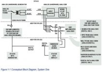
By the way, here is the block diagram of the Audio Precision System One.
It clearly shows that even the System One can do the same measurement procedure you list above. Analog generator --> DUT --> Analog notch filter --> A/D --> FFT.
Attachments
Ok, after having read through the System One's manual (it's only 571 pages), here's proof positive that even the System One is capable of performing the same type of measurement as John is doing.
From pages 11-4 and 11-5 (Chapter 11, Spectrum Analyzers):
Analog/Digital Input Selection
All the FFT-based programs can acquire digital signals (two
channels) directly from any of the digital interfaces of System One Dual Domain, and analog signals (two channels) via built-in 16-bit A/D converters. The Input control near the top of the Digital Analyzer panel permits selection of Digital or A/D. Click on the down arrow at the end of the field, then click on the desired input domain.
Analog Input Selections
When "A/D" is selected in the Input field, the Ch 1 and Ch 2
Source selections are Anlr A, Anlr B, Anlr Reading, Gen Mon, DSP A,
DSP B, and None.
"Anlr A" and "Anlr B", respectively, connect the Ch 1 and Ch 2 A/D converter inputs across the System One Analog Analyzer input channels at points following the input ranging circuitry. These are essentially the same points monitored by the front panel Channel A and Channel B Monitor Output BNC connectors. They are thus nearly-constant amplitude versions of the input signals following any required gain or attenuation and balanced-to-unbalanced conversion, but before any other signal processing such as filtering.
The "Anlr Reading" selection connects the Ch 1 and/or Ch 2 A/D converter input to the final analog signal in the System One Analog Analyzer, following all signal processing including the bandpass/bandreject filter, built-in low pass and high pass filters,
optional filters or the external filter, and also following all signal
processing of the IMD analyzer option or the Wow and Flutter option. This signal thus consists of harmonics and noise in THD+N mode, intermodulation distortion products in each IMD mode, the wow & flutter signal from the discriminator in W&F mode, and is band-limited by the filters selected in any mode.
So there you go, Charles. Just set up your analog generator and analog analyzer for your typical THD+N measurement using the analog analyzer's band reject filter to notch out the fundamental (it can be set to track the signal generator's frequency).
Then load up the FFTLSIDE or FFTGEN programs, set the source to "Anlr Reading" and off you go.
se
Steve Eddy said:So there you go, Charles. Just set up your analog generator and analog analyzer for your typical THD+N measurement using the analog analyzer's band reject filter to notch out the fundamental (it can be set to track the signal generator's frequency).
Then load up the FFTLSIDE or FFTGEN programs, set the source to "Anlr Reading" and off you go.
se
thanks for the good work (and reading through that 571-page manual), se.
Now, Charles, do you agree with se?
By the way, just got off the phone with Sound Technology (I'd called yesterday and left a voicemail message and they returned my call this morning).
Even though the website uses the words "manufactures" the 1700 series isn't exactly in current production, though they still build some for the government (they still have a stockpile of original parts and components). The price list is for refurbished units.
I also found out that the 0.0009% spec that Charles made reference to is for the 1701A "Precision Distortion Measurement System," not the 1700B.
I was told that the 1700B specs at about 0.002% (actually it ranges from 0.0018% to 0.0025%) for the generator and the same for the analyzer. So all told, you're looking at about 0.004%.
se
millwood said:thanks for the good work (and reading through that 571-page manual), se.
Thanks. Though I didn't read through all 571 pages. I don't quite have THAT much time on my hands.
I just read through enough to find the portion of the manual which unambiguously shows that even the System One can do the type of measurement that John's doing.
Now, Charles, do you agree with se?
This has nothing to do with agreeing with me. It has to do with whether or not an AP rig can do the same type of measurement that John's making. Whether it can or not has absolutely nothing to do with me. Either it can or it can't. Period.
So it's more a matter of whether Charles agrees with the System One's user manual.
se
It is strange when people discuss test equipment that they have no experience with.
First, the 1700B is spec'd at: .0018% harmonic distortion at mid frequencies. So far as my experience is concerned, this includes the oscillator as well as the analyzer section.
The FUNDAMENTAL limitation of this system's measurement capability is the NOTCH. It is the fundamental limit and is almost all the meter reads, except for noise at low levels. After all, a -95dB notch is slightly less than .002% You can't measure with the meter alone, lower than the notch itself.
This can be seen with ANY spectrum analyzer, FFT, or wave analyzer. The added distortion components from the oscillator or the input stages are lower in level by a significant amount. I have further improved the performance by upgrading the input and oscillator op amps.
Steve Eddy is not an 'objective' arbitrator here. He minimizes the quality of the equipment, and its cost to duplicate it. In fact, if it is so cheap to obtain a ST1700B, then why doesn't he buy one, if only to pick it apart? He could always sell it off later. Steve Eddy has little or no idea of what he is talking about in this case, but that won't stop him from confusing the rest of you.
- Status
- This old topic is closed. If you want to reopen this topic, contact a moderator using the "Report Post" button.
- Home
- General Interest
- Everything Else
- Cable Distortion Measurements: Part Deux