I have a great graphical EQ that displays 8 freq using 6 led's. It currently uses 5mm leds and each gets around 2 volts. Most likely they are .20MA
I would like to take away a couple bands, maybe the highest, lowest and one in the middle and go down to 5 led's. So it will be a 5x5 graphical eq (spectrum analyzer)
I would like to change all the LEDs to 8mm Straw Hat Wide Angle White LED - Ultra Bright LEDs using 100-120ma and 3.2 - 3.6v.
I can't believe it, but they actually light up dimly when I swapped 1 row of them out, I would just like for them to have the max brightness.
I have attached the schematic and parts list, any help would be greatly appreciated.
Bryan
Attachments
'Bright LED' has two meanings:
1. brighter than an average LED at a particular lowish current.
2. capable of being very bright given a big enough current (that would kill a normal LED).
I fear you may be confusing these two meanings. The circuit diagram is difficult to read, but somewhere in it there will be some means to limit the current in the LEDs. You need to modify this, while keeping within the capabilities of the driving chips.
I think what might actually be driving the LEDs is the CD4028BF. That seems to have plenty of power, but I am not 100% sure that is the role of that IC. It looks like the lm3915 is switching the negative on and off and the cd4028BF is providing the + voltage. There is a 10k resistor between each of the pins and a bc337 transistor:
I am not sure if that will help.
Thanks!
Bryan
- Collector-Emitter Volt (Vceo): 45V
- Collector Current (Ic): 0.8A
- hfe: 100-250 @ 100mA
- Power Dissipation (Ptot): 625mW
- Current-Gain-Bandwidth (ftotal): 210MHz
- Type: NPN
I am not sure if that will help.
Thanks!
Bryan
I added a jumper on each side of the 10k resistors and it actually made them less bright. I shorted out a row of LEDs and that made the rest brighter... I guess if the power dissipation is 625mW and there are 6 LEDs in a column, that could explain why the brightness is low? Each LED I am trying to use consume between 100-120ma. The voltage required is 3.2 - 3.6, but it seems like they are only getting around 2v. Could that be the problem? I am surprised they even lit up honestly. Not sure how to get the voltage and Ma up.
I have uploaded them here. Any help would be GREATLY appreciated.
So the problem is not on the power end, but the grounding end on the lm3915 because it will only go up to 30ma?
http://reactivelights.com/eq1.jpg
http://reactivelights.com/eq2.jpg
I am wondering what resistors I can use for R45 and R46 to get the max
So the problem is not on the power end, but the grounding end on the lm3915 because it will only go up to 30ma?
http://reactivelights.com/eq1.jpg
http://reactivelights.com/eq2.jpg
I am wondering what resistors I can use for R45 and R46 to get the max
Those scans are much more legible. The use of the transistors seems odd; they can't turn on fully. If the gain is 100, you'll see at least a couple of volts across them when driving an LED at 10 mA or so. I suppose that's "good enough" for the stock application, and maybe it helps to drop some voltage across the transistors rather than heating up the LM3915.
So, I'd add an open-collector inverting buffer to the 4028 outputs, and use those to pull down the bases of a set of PNP transistors, possibly TO220 package power transistors so as to have the option of driving 1W LEDs.
The LM3915 outputs would need pull-up resistors, then an inverting buffer could drive a set of NPN transistors. If the display operates in dot mode, a resistor would be sufficient to set the LED current, but in bar mode it would be best to modify the transistor drivers to act like constant current sources or sinks.
Alternatively, maybe it would be more sensible to omit the inverters, and let the LM3915 pull down the PNP transistors coming from +12, and the 4028 drive the NPN transistors. Unless I've overlooked some reason this won't work. It's late and I haven't had my dinner yet.
I will compare your RTA display with the Goldline RTA that I've been slowly building. Maybe they're similar enough that I can create a circuit that will allow either of them to drive higher power LEDs. I'd like to have the option of plugging it into a large wall-mounted display.
Hey Dangus, here are some more photos. Do you think you would be interested in helping me with this project? I will pay you for your time. Here are photos of the board:
http://reactivelights.com/1.JPG
http://reactivelights.com/2.JPG
http://reactivelights.com/3.JPG
http://reactivelights.com/4.JPG
http://reactivelights.com/5.JPG
http://reactivelights.com/6.JPG
http://reactivelights.com/7.JPG
I am also making a 6' wide by 4' tall EQ for my wall. I will take a picture of the frame and artwork for you to check out.
I need this circuit to be 5x5 and have the brightest LEDs as possible. You can scrap this board all together if you think there is an easier way to get the job done.
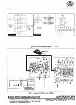
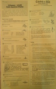
I am about to test this 3-channel / 15-led audio spectrum display / vu-meter.
If you think it would be easier to add 2 more channels / frequencies, I would way prefer to use this vs using the LM3915.
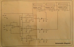
I can send the schematic as well, but maybe I should test it first:
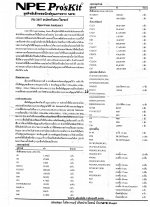
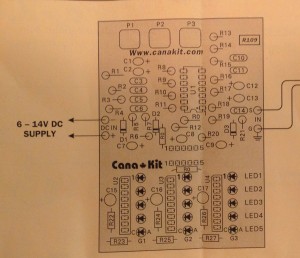
CanaKit CK109 - 3-Channel / 15-LED Audio Spectrum Display / VU-Meter (Electronic Kit - Requires Assembly)
Thanks!
Bryan
http://reactivelights.com/1.JPG
http://reactivelights.com/2.JPG
http://reactivelights.com/3.JPG
http://reactivelights.com/4.JPG
http://reactivelights.com/5.JPG
http://reactivelights.com/6.JPG
http://reactivelights.com/7.JPG
I am also making a 6' wide by 4' tall EQ for my wall. I will take a picture of the frame and artwork for you to check out.
I need this circuit to be 5x5 and have the brightest LEDs as possible. You can scrap this board all together if you think there is an easier way to get the job done.
I am about to test this 3-channel / 15-led audio spectrum display / vu-meter.
If you think it would be easier to add 2 more channels / frequencies, I would way prefer to use this vs using the LM3915.
I can send the schematic as well, but maybe I should test it first:
CanaKit CK109 - 3-Channel / 15-LED Audio Spectrum Display / VU-Meter (Electronic Kit - Requires Assembly)
Thanks!
Bryan
Might have the same problem with the amount of power that goes through the IC AN6884, which would also require the use of transistors to supply sufficient grounding
AN6884 datasheet(1/4 Pages) PANASONIC | 5-Dot LED Driver Circuit
AN6884 datasheet(1/4 Pages) PANASONIC | 5-Dot LED Driver Circuit
The circuit in post #1 is suspiciously similar to the Rim Electronic NFA100. In the NFA100 you could change the LED current by changing 10 resistor values. Also the octave filers seem a little more sophisticated. E
I couldn't find any information on this, could you post a link to more information or a schematic. Thanks!!! I think I have to give up on the original one using the LM3915. The LM3915 is getting crazy hot with different LEDs in there and I really don't want to add more components to the mix.
The Gold-Line RTA that was published as a project in Popular Electronics (Sept 1979) uses a very similar multiplexed display (7 levels, 10 bands). Transistors are 2N3904, but without any resistors between the driving IC (4017 CMOS) and the transistor bases, but there are 180 ohm resistors in series with the emitters. Those resistors would dissipate some of the power that would otherwise heat up the LM3915.
The AN6884 is limited to 15 mA drive, so if you want to drive high power LEDs, you'll need separate transistors, one per LED, and something to limit the current.
I said "something" because there are linear current sink chips used in LED drivers, like the AMC7135 which is fixed at 350 mA. Usefully, they also have a supply/control pin which can be used to dim them via PWM, if 1 W turns out to be too bright. The supply voltage is limited to 6V, but it wouldn't be a bad idea to run the LEDs from 5V (or less) and waste less power. PWM dimming could be done in other ways (perhaps using an enable pin on the column select IC in a multiplexed display).
I'm not going to make any promises, but it does seem like we share a common interest in having a high power LED RTA display. So, if I get as far as designing a PC board, I'll keep in mind the requirements of your RTA board as well as the Gold-Line RTA (and any other kit like the NFA100 if a schematic is available). 1 watt LEDs may be overkill for home use, but it may be feasible to use a matrix of them fitted with narrow beam optics to project a display onto a wall, or mount them behind a sheet of scrim.
Thanks Dangus for all the help. I ran a test last night using the 100-120ma LEDs on the CanaKit CK109 - 3-Channel / 15-LED Audio Spectrum Display / VU-Meter (Electronic Kit - Requires Assembly). and it worked out pretty well.
I am sure I am overloading something as I just swapped the LEDs. I have an event I will be attending in about a month, so I am really hoping to have something ready for the event.
I will take some pictures tonight, since I forgot last night. The display is fairly large.
For now I am holding off on the board with the LM3915. Until I can learn a little more about providing more power and grounding without overheating the LM3915, it will be on the back burner. (unless this new board I can't get 5 frequencies out of)
The great thing about the LM3915 is the huge display that reacts very well to music. I will probably make a wall version of it in the future without getting rid of any of the bands or LEDs.
So for now I am looking to add 2 more bands to the CanaKit board or using my 2nd kit and change the frequencies a little. Now that shouldn't be too difficult. I wish I brought the info sheet and schematic to work, but I will put it up this evening as well if anyone wants to take a look at it.
http://canakit.webstorepowered.com/CanaKit-CK109-3-Channel-Spectrum-Electronic/dp/B006L7RVYY
My third attempt to get back. If the computer crashes again it will do this also physically!
Rim Electronic joined so many, many other electronic suppliers in electronic supplier heaven. But I have the schematic and a write-up in German. I will email them to you if you pm me your email addresses. I don't belive the mean mods would like me to post it here.
I am partway through a pcb design for my version of the NFA100. Filter and display boards are finished, input,control board part way. The finished boards will go into a handheld box (Pactec K-TT-9VB). The circuit is a bit dated (it also uses the LM3915), but it is a neat DIY project and I like them blinky lites! E
I will PM you my email. Here are photos of the new kit and my eq. It is BIG! The artwork is backlight vinyl. Hopefully will start on making individual boxes for the LEDs soon. Mainly posterboard hot glued.
Should be fun!
If anyone has any input about how to change the frequencies / bands on this kit, I would really appreciate it. Gonna dig in to the schematic later 2nite to see if I can figure it out.
Thanks!
Crap. Forgot I have to upload the images first.... Will post a new message with the images.
Should be fun!
If anyone has any input about how to change the frequencies / bands on this kit, I would really appreciate it. Gonna dig in to the schematic later 2nite to see if I can figure it out.
Thanks!
Crap. Forgot I have to upload the images first.... Will post a new message with the images.
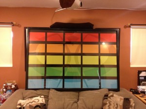
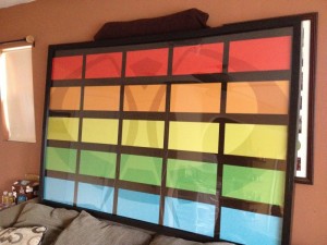
Those images are too small to be legible; could you repost them bigger? (They don't have to be 1200 dpi, though - 300 is usually OK) That big display should look awesome. It reminds me of a vintage Teac cassette deck that had similar multicoloured lamps (not LEDs) for the VU meters.
Teac V-9 Stereo Cassette Deck
To add more bands, add another couple of opamps, and the LED drivers. The frequencies are determined by bandpass filters; you should be able to calculate the centre frequency and stuff from the values. I'd imagine that the bass is tuned for high bass (kick drum); if I was adding another bass channel, I might tune that to the low shuddering bass, like around 40 Hz (or about an octave lower). So, simply doubling the capacitor values would probably get you there.
If you wanted more brightness, adding extra LEDs in series would contribute more light without drawing any extra current, since they'll just take some of the voltage that was being dropped already in the driver (or series resistor, if any). Which would also mean less heat dissipated by the driver chip.
- Status
- This old topic is closed. If you want to reopen this topic, contact a moderator using the "Report Post" button.
- Home
- General Interest
- Everything Else
- Circuit Help needed for graphic equalizer using LM3915