I'm just Mr. Cut-n-Paste these days ... I learned how to use Paint!
TBA231:

View attachment TBA231.pdf
It will depend on how your circuit uses pins 2, 3, 4, and 10, 11, 12 of the TBA231.
This probably won't be an easy swap ...
TBA231:
View attachment TBA231.pdf
It will depend on how your circuit uses pins 2, 3, 4, and 10, 11, 12 of the TBA231.
This probably won't be an easy swap ...
Last edited:
Apart from the compatibility issue, one of those socket whatevers, a piece of perfboard and a plain 8pin socket would do...
Andreas
Andreas
1) why?I want to replace the IC TBA231 with OPA2134. TBA 231 is mounted in a 14 pins holder, while OPA 2134 stop at 8. Does there exist a adapter that convert from 14 to 8 pins?? If so, where can I get in?
Other good suggestions will be received with thanks.
Eivind Stillingen
2) what do you expect to achieve?
3) post the schematic where you intend to replace it
4) in a nutshell, you can not pull a TBA231 and plug a different one in there, even if you had a proper "pin rerouting" socket .

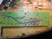
Back in the 70's I built a Sentec SE77 preamplifier (Swedish). This was one of my very first DIY projects. Since then, there have been many more. This preamplifier had as many others, to give way to new and more interesting projects later on, and has since been stored in my garage. As part of a larger “clearing projects” in older DIY projects, I brushed the dust of this preamplifier. To update SE77, I have been inspired by this: www.svalander.se/tips_fakta/hifi-tips/elektronik/modifiering_sentec/
Sorry that this is only written in Swedish, which is a easy thing for us Norwegians to understand.
I have, after I asked my question on this site, sat down for to maybe find a workable solution. See attached photo where I have made a "test" on a veroboard and with a NE555.
Since there is no more modern subsitutes for a 14 pin TDA231, I want to go for OPA 2134
Comments are welcome.
Attachments
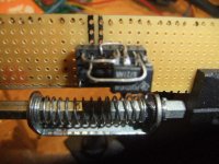
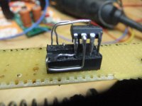
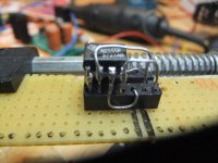
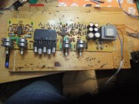
To be honest, the 'test' looks a bit crude to me
I think I wouldn't solder directly to the pins of the replacement opamp, but use a socket for it instead. Use a 14pin socket adapter as shown above, reroute the needed pins on a small piece of veroboard and put a 7pin socket adapter on it for the new chip.
More difficult, but probably will look nicer and work more reliable in the end.
Regards,
Andreas
- Status
- This old topic is closed. If you want to reopen this topic, contact a moderator using the "Report Post" button.
- Home
- General Interest
- Everything Else
- Adapt 14 pins into 8 pins