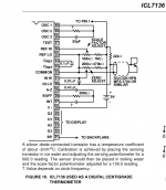
I have an ICL7136 3½-digit a/d converter chip and I would like use it as a thermometer. The datasheet features a suitable circuit for measuring temperature with a diode-connected npn transistor.
The problem is that the ICL7136 features outputs for driving a 3½-character lcd screen, while I would like to use two or three 7-segment led displays (common anode) for displaying the temperature. Intersil's application note mentions that the IC outputs ~3.5V(rms) AC for driving the lcd.
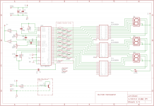
Would it be possible to use three ULN2803 Darlington transistor arrays to drive led displays with this chip, like in the schematic?
Attachment #1 shows the circuit I drew with Eagle. It still needs a power supply and another three current-limit resistor networks...
The problem is that the ICL7136 features outputs for driving a 3½-character lcd screen, while I would like to use two or three 7-segment led displays (common anode) for displaying the temperature. Intersil's application note mentions that the IC outputs ~3.5V(rms) AC for driving the lcd.
Would it be possible to use three ULN2803 Darlington transistor arrays to drive led displays with this chip, like in the schematic?
Attachment #1 shows the circuit I drew with Eagle. It still needs a power supply and another three current-limit resistor networks...
Attachments
Thanks for your reply. I have realized that it might be very troublesome to interface an led display with lcd drive circuitry. I need to get an lcd display to use with this chip or use another a/d-converter/display driver IC that has 7-segment led output.The signals driving the LCD are multiplexed aound the BP output and your design will not work.
Gajanan Phadte
If you can accept a display that is not very bright, there is a possibility: you can drive directly LEDs at low current.
To do that, you need a high brightness LED display, one that gives acceptable luminosity at 1mA, a common cathode one, you dimension the segment resistors to give 3 mA and you buffer the BP common with a PNP emitter follower to drive the common cathode.
The peak current in the segment will be ~2mA, due to the internal resistance of the drivers, and the average current will be half of that due to the LCD type drive, but it will work, I have already used such a configuration.
Thanks for your tip!If you can accept a display that is not very bright, there is a possibility: you can drive directly LEDs at low current.
To do that, you need a high brightness LED display, one that gives acceptable luminosity at 1mA, a common cathode one, you dimension the segment resistors to give 3 mA and you buffer the BP common with a PNP emitter follower to drive the common cathode.
The peak current in the segment will be ~2mA, due to the internal resistance of the drivers, and the average current will be half of that due to the LCD type drive, but it will work, I have already used such a configuration.
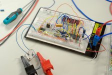
I assembled the circuit on a breadboard. I used a 2N2907A transistor to buffer the 'BP' pin to drive the led displays. I experimented with a 2N2222A signal transistor and also with an MJ15003 power transistors for sensing the temperature. It works very well, although the display segments are quite dim (as expected).
So I may need to try if the display segments could be buffered with some transistors for increased brightness. Or just get the chip which has led segment drivers built-in.
So I may need to try if the display segments could be buffered with some transistors for increased brightness. Or just get the chip which has led segment drivers built-in.
Attachments
That's the sensible solution if your display is not bright enough to your taste: adding 23 buffers is not reasonable, unless you have no other choice.Or just get the chip which has led segment drivers built-in.
Note that some modern displays can be quite bright with only 1mA average current; yours look like standard-brightness types.
Even a 7107 will not be that much brighter: 8mA instead of 1 looks like a lot, but the eye response is logarithmic, and the BP strobing also increases somewhat the perceived brightness.
Thanks for the answer.
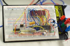
I made the following circuit in breadboard:
Digital thermometer with LED / LCD display
Using the LED version, and changing R1 to 100k, since I had this in hand. I used the ICL7106 chip.
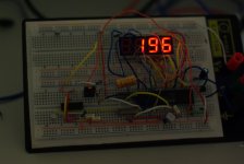
Result? It did not work. Sometimes nothing was indicated in the 7-segment leds, sometimes there were some indications - but they where constantly changing (in a flashing manner - like the indications followed a clock, but not a strict one) and obviously wrong, since I wasn't able to calibrate it. Any ideas? Does this circuit seem to have any flaws? I am not familiar with such chips yet.
Maybe the problem is the breadboarding itself - if that's the case, I will just solder it. Does anyone have any ideas? Thanks in advance!
I made the following circuit in breadboard:
Digital thermometer with LED / LCD display
Using the LED version, and changing R1 to 100k, since I had this in hand. I used the ICL7106 chip.
Result? It did not work.
Sometimes nothing was indicated in the 7-segment leds, sometimes there were some indications - but they where constantly changing (in a flashing manner - like the indications followed a clock, but not a strict one) and obviously wrong, since I wasn't able to calibrate it. Any ideas? Does this circuit seem to have any flaws? I am not familiar with such chips yet.Maybe the problem is the breadboarding itself - if that's the case, I will just solder it. Does anyone have any ideas? Thanks in advance!
You should use the schematic given in the datasheet rather than rely on something found on the www. Fig 18: www.intersil.com/data/fn/fn3082.pdf
Thanks! I will try to solder that circuit this time.
A couple of trivial questions:
(1) I have a BC327 at hand that I plan to use as the sensor. I bought it for my previous try. It should be ok, right?
(2) Is current to the 7-segments limited internally by the ICL7106? I don't see any resistors limiting the current to each 7-segment.
(3) What is the backplane pin of the IC? (in figure 18) On the other site, the schematic stated that you should connect the emitter of the buffer driving the anodes. Correct or not?
Thanks in advance!
- Status
- This old topic is closed. If you want to reopen this topic, contact a moderator using the "Report Post" button.
- Home
- General Interest
- Everything Else
- ICL7136 thermometer, LED display