Here's another amp
Very interesting input from everyone.
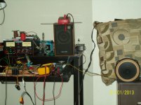
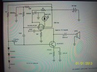
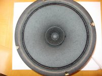
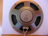
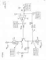
Here's the schematic of what I call an humble amp. It is very simple and sounds good. If anyone tries it out, just be sure to run the bias up from 0 V slowly until it settles. you need about .14 - .15 volts on the emitter. Then, you should not have to make anymore adjustments for awhile. I have thought of some variations, but for now this is satisfying. Use efficient speakers. Shown is one of my Jim's Audio P-610st drivers being broken in before measurement.
Happy 2013
Terry
Very interesting input from everyone.
Here's the schematic of what I call an humble amp. It is very simple and sounds good. If anyone tries it out, just be sure to run the bias up from 0 V slowly until it settles. you need about .14 - .15 volts on the emitter. Then, you should not have to make anymore adjustments for awhile. I have thought of some variations, but for now this is satisfying. Use efficient speakers. Shown is one of my Jim's Audio P-610st drivers being broken in before measurement.
Happy 2013
Terry
Attachments
Antoinel,
Not surprising--but I have wondered what the effects are with plate and screen voltages in place with their bypasses, and sufficient bias applied to grid via cathode resistor or LED are. I will post the scheme of my amp soon, just having trouble finding the time anymore! I am making an assumption of course, that you observed voltages on the tubes pins without any of the above mentioned voltages in place---or perhaps you had applied voltages?
This is interesting to me as it will be instructive to learn the nature of what any feedback is, whether it be degenerative or regenerative, or possibly some wacky combination of both. All I know is, the amp sounds better than I thought it should. What amp? Well, I will try to post the schematic tomorrow.
What type of speaker are you using and how loud will it go? Is it driven well enough, or do you feel some pre-amplification is in order?
Thanks and Happy New Year!
Terry
Parasonic. All of us are on a roll. Thank you for the pictures of your amp. The LED glows mighty bright. Here are answers to your questions above:
- The voltages on the cathode, grid and plate were a consequence of the modulated heater current. No external [bias] voltages to the tube's electrodes were applied.
- A picture of the full range 8 Ohm Radio Shack [Realistic and not Archer brand] is attached. Its loudness was adequate when hung in free air mode, and not boxed.
- Please go to the Headphone Systems Forum. Search for my username. Locate the topic "Does anyone make their own headphones?". I describe [with pictures] therein a bicycle helmet headphones using 4 " full range and 8 Ohm loudpeakers. In this current app, they were connected in series for a 16 Ohm load. Plenty of high fidelity SPL.
- I also have Grado SR80i headphones
- LM386 is the preamplifier. It has a voltage gain of 20-200 in solo application. In my app it has a gain of 20 before Pass loop feedback.
- I will characterize each output separately with the above transducers with and without feedback.
- I will also remove one tube of the collector load so as to increase Vce of the power NPN which is now at ~6 VDC.
Attachments
The sound heard coming from your amp is most likely produced by the OPT. I have some OPT's that are rather loud and some totally quiet. Loud ones can sometimes be quieted by jamming something between the bobbin and the core. Sometimes the windings themselves produce sound.
It is common for tubes to produce random sounds associated with thermal expansion. Sometimes these sounds wind up in the speakers at a low volume.
I have never heard music come from a tube, but if one had something inside that was free enough to vibrate, it would be a better microphone than speaker. I have a Motorola branded 6SN7 that is microphonic enough that you can talk to it and hear yourself in the speaker. Turn the volume loude enough and acoustic feedback occurs.
Very cool! Happy new year George!
Performance of Amp
A happy, safe, healthy and prosperous 2013 to everyone. The attached picture is one of many which characterizes the performance of the shown amp [schematic]. I'll refer to this amp as A1. Please note the following:
A happy, safe, healthy and prosperous 2013 to everyone. The attached picture is one of many which characterizes the performance of the shown amp [schematic]. I'll refer to this amp as A1. Please note the following:
- A dual +/- 15 VDC regulated power supply was used. No hum or noise at the collector and emitter nodes.
- One 12AX7 was used for the emitter load and another 12AX7 was used for the collector load.
- The heaters of each 12AX7 were operated in parallel; meaning ~300 mA idle current flowed through each. The value of each load resistor [heater only] was ~20 Ohms.
- Ve is the idle DC voltage at the emitter node = 5.6 V. It follows by oscilloscope measurement that the maximum unclipped peak to peak Voe was = 10 Vac in the frequency range of 30 -150 Hz. This is the same as saying that the useful unclipped peak to peak current flowing through the output stage was equal to 500 mA.
- Voltage measurements were taken at the five nodes in A1; namely Vi, Ei, Eo, Voc and Voe. These measurements and further algebraic calculations thereof characterize the operation of A1
- A1 was operated open loop; meaning the switch in the Pass feedback loop was open.
- The voltage gain of A1 is Voc divided by Vi. Or 1.05 V/0.183 V = 5.7
- Mentally disconnect the load = 8 Ohms. It follows that the new Voc must equal Voe. Thus voltage gain of A1 when Z load = infinite is 3.84 V divided by 0.183 v = 21 which is the ~ specified gain of LM386.
- The equivalent collector load is 8 Ohms in parallel with the 20 Ohms heater resistance = 5.7 Ohms. The numerical ratio of 20 ohms to 5.7 Ohms [3.5] is ~ equal to the ratio of Voe [3.84] to Voc [1.05] = 3.7. The numbers ~jive.
- The voltage gain of LM386 is Eo [3.97 V] divided by Vi [0.183 V] = ~22
- Close the Pass feedback loop.
- The voltage gain of A1 is still Voc [0.81 V] divided by Vi [0.165 V] equal to 4.4. This is a 23% loss in the parent original gain; albeit put to good use via Pass feedback to lower distortion, and output impedance etc..
- The voltage gain of LM386 is Eo [2.97 V] divided by Vi [0.165 V] = 18; apparently reduced from the parent 22 due to feedback.
- Open the feedback loop
- Adjust Ei to 0.135V like its value in Experiment #2
- The voltage gain of A1 is Voc [0.82 V] divided by Vi [0.136 V] = 6.0; roughly similar to that calculated in Experiment #1 of 5.7.
- The voltage gain of LM386 is Eo [2.98 V] divided by Vi [0.136 V] = 22 like found in Experiment #1. The numbers jived again.
- Z Load equal to 32 Ohm non-inductive
- Z load equal to that of a full range 8 Ohm loudspeaker in the frequency range of 30 -150 Hz.
Attachments
Last edited:
Good
Thanks for the analysis Antoinel. I'd like to put one together when I have time. (work just tires me out to where I don't care if anything gets done when I get home!)
I'd like to try it with some AN214 I have. Have you tried auto lamps? (somebody I think mentioned those). I threw together a little NPN based SE amp a few years back and played around with Wagner 2004 (I think is what they were)as collector loads. Had to parallel a couple of them as I remember and was 12 volt supply. Worked --but really lit up the room.
Good luck in your experiments.
Just a side note on the humble amp--I currently am using RCA 15CW5 and a plate load resistor of 1.5K ohms works better there instead of 2.2K ohm. This will be somewhat tube dependent. I've not tried any grid stopper resistance--yet.
Cheers
Terry
Parasonic. Thank you for your reply. Maybe in the long haul, the title of this thread will morph to " Incandescent Lamp Loads" so as to accomodate lamps in general. Fluorescent and Neon types are another matter and will be studied in good time. I have not tried auto lamps. A typical Halogen headlamp is specified at 12 V and 50 Watts; 4A at full brightness. Smaller wattage bulbs are rated at 7 W; ~0.5 A. Workable.Thanks for the analysis Antoinel. I'd like to put one together when I have time. (work just tires me out to where I don't care if anything gets done when I get home!)
I'd like to try it with some AN214 I have. Have you tried auto lamps? (somebody I think mentioned those). I threw together a little NPN based SE amp a few years back and played around with Wagner 2004 (I think is what they were)as collector loads. Had to parallel a couple of them as I remember and was 12 volt supply. Worked --but really lit up the room.
Good luck in your experiments.
Just a side note on the humble amp--I currently am using RCA 15CW5 and a plate load resistor of 1.5K ohms works better there instead of 2.2K ohm. This will be somewhat tube dependent. I've not tried any grid stopper resistance--yet.
Cheers
Terry
I'll briefly digress from my plan above, and connect voltages to one of the twin triodes in the emitter leg; max plate to cathode voltage will be 30 V for the time being.
An output stage like that of A1 maybe useable as the driver stage in a JLH and/or a PLH type amplifiers. Infuse their great parent sound with incandescent sonics; be it from lamps or vac tube heater loads. I' ll work a schematic on paper.
Best regards.
Energizing the vac tube connected to emitter
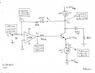
I imposed voltages on the "bottom" 12AX7 and operated it in the "common grid " configuration. The attached picture shows the partial schematic of A1 amp with particular focus on the operation of the vacuum tube. Note the following :
Suppose a high power tube was used in a common grid configuration such that its cathode is connected directly to the emitter node [+5.6 Vdc] and its plate voltage at >100 Vdc. In a previous post, Voe was shown to swing 10 Vp-p. Will this be useful in power amplification?
Best regards
I imposed voltages on the "bottom" 12AX7 and operated it in the "common grid " configuration. The attached picture shows the partial schematic of A1 amp with particular focus on the operation of the vacuum tube. Note the following :
- Grid was grounded [at -15 Vdc regulated].
- The voltages at the cathode were +0.37 Vdc and 0.015 Vac [100 Hz] as measured by the AC multimeter. The value of the cathode resistor was 0.56 KOhms
- Plate voltage was +15Vdc regulated. The attendant calculated idle plate current was 0.124 mA
- Plate voltage was = 0.1 Vac by AC multimeter and simultaneously equal to 0.3 Vp-p by scope. Furthermore, plate voltage as seen on the scope was constant to 10 KHz.
Suppose a high power tube was used in a common grid configuration such that its cathode is connected directly to the emitter node [+5.6 Vdc] and its plate voltage at >100 Vdc. In a previous post, Voe was shown to swing 10 Vp-p. Will this be useful in power amplification?
Best regards
Attachments
A1 amp driving a full range loudspeaker
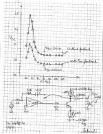
In Post 24, the performance of A1 was characterized with an 8 Ohm non-inductive power resistor in the frequency range of 30 -150 Hz. The test equipment worked very well, and the results appeared to be reliable. In this post, amp A1 energized a 15 inch, full range musical instrument [8 Ohm; MCM Electronics part # 55-1310]. The results of this study are shown in the attached picture. The top portion shows the power output voltage data [Voc] before and after Pass loop feedback as a function of frequency in the range of 30 - 150 Hz. The bottom part of the picture shows a simplified schematic of the circuit used. Please note the following results:
Best regards
In Post 24, the performance of A1 was characterized with an 8 Ohm non-inductive power resistor in the frequency range of 30 -150 Hz. The test equipment worked very well, and the results appeared to be reliable. In this post, amp A1 energized a 15 inch, full range musical instrument [8 Ohm; MCM Electronics part # 55-1310]. The results of this study are shown in the attached picture. The top portion shows the power output voltage data [Voc] before and after Pass loop feedback as a function of frequency in the range of 30 - 150 Hz. The bottom part of the picture shows a simplified schematic of the circuit used. Please note the following results:
- Without feedback [pull 22 uF capacitor from proto board], the collector is a current source output port. Because it gave a voltage profile like that of the typical impedance curve of an woofer. The resonance peak occured at 40 Hz, and the voltage ratio of peak to the average in the plateau [90 -150 Hz] is 2.1.
- With Pass loop feedback, [install 22 uF capacitor back in circuit], the attendant graph showed that the collector is still a current source output. However, the voltage ratio of peak [at 40 Hz] to that in plateau decreased to 1.7. With and without feedback are expected to sound different.
- Loss in voltage gain [due to feedback] may be tentatively taken to also mean that utilized constructively to improve the linearity and lower the distortion of A1. Numerically, it is {Voc before feedback [1.2] minus Voc after feedback[0.91]} divided by Voc before feedback [1.2]. The answer is 0.24. This is a 24% reduction in voltage gain. Since the result is a ratio of voltages, then 20 x Log 0.24 = 12 dB. Or one may see it as simply the ratio of Voc after feedback [0.91] divided by Voc before feedback [1.2] = 0.76; or the gain after feedback is down to 76% its no feedback value.
Best regards
Attachments
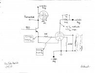
Here is a very simple and cheap PS and regulator
In keeping with the budget nature of humble, this PSU/ regulator sounds good with the amp. After trying several more complicated schemes, this one wins on sonics, no hum. Parts are readily available, maybe in the junk parts box. The reverse biased collector/emitter string works great, but I can't vouch for all species of 3906 that you may have. You can put them in series with a 330 ohm resistor and 36-37 VDC applied and you should see about 32 VDC across the string. Out of about 12 I had from the same vendor, you could interchange any 3 of them and obtain that voltage. Sometimes simpler is better.
Cheers
Terry
Attachments
You have an effective and simple solution. On several occasions, I used the reverse-biased base to emitter junction of power and complementary bjts [TO-3 pkg.] as power Zeners.In keeping with the budget nature of humble, this PSU/ regulator sounds good with the amp. After trying several more complicated schemes, this one wins on sonics, no hum. Parts are readily available, maybe in the junk parts box. The reverse biased collector/emitter string works great, but I can't vouch for all species of 3906 that you may have. You can put them in series with a 330 ohm resistor and 36-37 VDC applied and you should see about 32 VDC across the string. Out of about 12 I had from the same vendor, you could interchange any 3 of them and obtain that voltage. Sometimes simpler is better.
Cheers
Terry
Is it proper to say that an objective of your circuit is to introduce a characteristic tube-like sound in otherwise amplifying semiconductors; FETs or BJTs?
Best regards
Is it proper to say that an objective of your circuit is to introduce a characteristic tube-like sound in otherwise amplifying semiconductors; FETs or BJTs? Best regards[/QUOTE said:Hi Antoinel,
I wouldn't say that it is an objective, but it is a consequence of such a circuit. I don't have a large listening space, so I have had an interest in simple, mostly single ended designs. I listen at very moderate levels, and you can get away with little power in a small space. I like the idea of a tube driving a BJT for some reason, just a preference. With this recent amplifier, I am enjoying my music collection again very much, and that is with only one amp strung together on the desk, driving a Diatone "clone". I now have a stereo pair in the works. I don't like the idea of spending huge amounts of $$ on audio equipment. One of these days I hope to build a Nelson Pass design, when I can get the time and resources, but for now I am having a great time! (and isn't that what it is about?)
Terry
On engaging 12AX7 of Amp A1 in audio signal train
The classic hybrid designs of vacuum tubes and transistors have a common feature. The input signal is first amplified by tubes and then presented to a transistor power output stage. Examples are MOSKIDO, AIKIDO etc. The sound signature of the resulting hybrid amp is believed to be like that of an all tube design. The hybrids of Millett and Parasonic add another interesting feature to the classic designs by utilizing the amplifying tube heaters as loads to the transistor power output stage. Millett and Parasonic speculated about feedback from the heaters to the cathode etc..Both may have concluded that if present feedback was not relevant.
In this post, the reverse of the above practices was used instead. Please see the attached schematic. Here are the details:
Kind regards.
The classic hybrid designs of vacuum tubes and transistors have a common feature. The input signal is first amplified by tubes and then presented to a transistor power output stage. Examples are MOSKIDO, AIKIDO etc. The sound signature of the resulting hybrid amp is believed to be like that of an all tube design. The hybrids of Millett and Parasonic add another interesting feature to the classic designs by utilizing the amplifying tube heaters as loads to the transistor power output stage. Millett and Parasonic speculated about feedback from the heaters to the cathode etc..Both may have concluded that if present feedback was not relevant.
In this post, the reverse of the above practices was used instead. Please see the attached schematic. Here are the details:
- The input audio signal is amplified first by LM386 instead of a vacuum tube; be it that attendant to the emitter or collector of the NPN power output stage.
- The vacuum tube attendant to the emitter port is wired as a current source [cathode shorted to grid]. The twin triodes therein are connected in parallel. Their combined idle plate current was ~0.5 mA at idle.
- The cathode/grid of the equivalent triode was then connected to the output port of LM386. The signal output of LM386 modulated plate current; such that a signal appeared across the plate load [3.3K]. The emitter and base ports are also possible junctions to connect the cathode/grid of the equivalent triode.
- The plate signal was then fed back to the inverting port of LM386. This is the principal difference between the approach in amp A1 and the classic practices.
- The impact of the fed back signal was to decrease the power output signal e.g. at the emitter port. It was negative feedback. Clearly; I infused the solid state hardware with a triode signal; with a possible outcome of a net tube-like performace for amp A1.
- The connections at the non-inverting port of LM386 was that of Pass negative feedback as described in earlier posts. Its value is to recycle or rerun all signals one more time through the solid state devices and triode.
- Sounded great
Kind regards.
Attachments
Last edited:
The diagram in the above post showed the voltage output of the vacuum tube was fed back to the inverting input of LM386. This was negative feedback because it diminished the power out voltage at the emitter and collector ports. I asked myself what would happen if I connected the same voltage output of the vacuum tube to the non-inverting input of LM386 instead. First I disabled Pass feedback. I expected oscillation. Fortunately oscillation did not happen. But in this case of positive feedback the power output voltages at both of emitter and collector ports increased. I'll quantify the gain of amp A1 with positive and negative feedback ftom the triode.
I found a role or purpose for the triode attendant to its heater connected to the emitter of the transistor; namely this and the preceeding posts. What role can I expect the triode attendant to its heater connected to collector of the transistor ? I connected its grid to its cathode [one of the twins], and this joint was further connected to the output of LM386 like I did for the triode attendant to the emitter. Fortunately, this collector-triode performed like the emitter - triode for both negative and positive feedback. It is possible now to use a suitable light bulb and one 12AX7 [instead of two 12AX7s] at either emitter and collector ports. The light bulb can be incandescent [lit] or cold .
I found a role or purpose for the triode attendant to its heater connected to the emitter of the transistor; namely this and the preceeding posts. What role can I expect the triode attendant to its heater connected to collector of the transistor ? I connected its grid to its cathode [one of the twins], and this joint was further connected to the output of LM386 like I did for the triode attendant to the emitter. Fortunately, this collector-triode performed like the emitter - triode for both negative and positive feedback. It is possible now to use a suitable light bulb and one 12AX7 [instead of two 12AX7s] at either emitter and collector ports. The light bulb can be incandescent [lit] or cold .
The attached schematic demonstrates the meaning of the term Other in this thread's title "Other Applications of Vacuum Tubes". The tubes are used around the solid state circuitry to first generate signals, and then infuse this circuitry with these signals via positive and/or negative feedback. Note the following in the schematic.
Best regards
- PF means positive feedback. By contrast NF means negative feedback. One may apply NF or PF only and NF plus PF simultaneously.
- I have 4 functional triodes in the circuit of the NPN power output transistor.
- The grids and cathodes of the 4 triodes are tied together, and to the emitter of the transistor. This connectivity generates plate currents.
- The plate of the triode for the upper 12AX7 [PFu] and the plate of the triode for lower triode [PFl] are tied together.
- Ditto for the plate electrodes labelled NFu and NFl.
- *In a demo application, set Ve = 3 VAC at 100Hz. Apply NF only by joining the respective tube plates to the inverting port of LM386. Note that Ve drops to ~2.6 -2.7 VAC,
- *Now apply PF by joining the plates of the respective tubes to the non inverting port of LM386. Note that Ve is restored to 3 VAC like in the absence of both PF and NF.
- I chose [by trial ] the resistor values at the inputs of LM386 to give the response above [* bullet points] with simultaneous PF and NF.
- Can play more games with this topology. All or some of the plate signal outputs may be joined together for NF or PF; many possibilities etc..
- Amp A1 is stable as configured with simultaneous NF and PF. There was no oscillation or latch up.
- Amp A1 sounded great as configured.
Best regards
Attachments
ANT Negative Feedback
The title pertains to current feedback around a single power output semiconductor like a BJT, FET etc.. Please consult the attached schematic for its details. The NPN output stage shows half-shaded sine waves at its collector and emitter ports; which are out of phase. This is a prime candidate for a bridge amp; by simply connecting the load Z [or loudspeaker] between Vo and Ve. This is ANT Negative Feedback.
Here are the details of the attendant experiment and the resulting performance of this amp before and after bridging.
Best regards.
The title pertains to current feedback around a single power output semiconductor like a BJT, FET etc.. Please consult the attached schematic for its details. The NPN output stage shows half-shaded sine waves at its collector and emitter ports; which are out of phase. This is a prime candidate for a bridge amp; by simply connecting the load Z [or loudspeaker] between Vo and Ve. This is ANT Negative Feedback.
Here are the details of the attendant experiment and the resulting performance of this amp before and after bridging.
- Disable all positive and negative feedback emanating from the plates of the vacuum tubes [as shown in the previous post]. To simplify analyses. Can easily restore feedback from vac tube at any time/later.
- Connect the load Z [e.g. 33 Ohms] to ground [No ANT Feedback].
- Set function generator frequency to 100 Hz.
- Adjust the input signal Vi to the non-inverting input of LM386 to get 3.85 VAC at the emitter [Ve] of the NPN transistor. This and all voltage measurements were done with a Micronta digital voltmeter. Log voltage value in Table 1.
- Simultaneously monitor this output signal [Ve] on the scope. The scope read 10 Vp-p, and the signal was not and must not be clipped.
- Measure Vo across the load and log its value in Table 1.
- Apply ANT Feedback by connecting the load Z [33 Ohms] between Vo and Ve. The scope showed a clipped Ve output signal.
- Lower next the level of input signal [Vi] to LM386 until the signal on the scope is restored to the clean shape of a sine wave.
- Measure the voltage at the emitter of the BJT [Vef; f for feedback] and across the load Z [Vof-Vef]. Log their values in Table 1.
- Repeat the above protocol for the remaining load resitances to complete Table 1.
Best regards.
Attachments
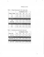
The attached jpg and identical pdf are magnified Tables 1 and 2 shown in the above post.
Q: Why did I choose this range of load resistors Z?
A: Ignoring Z= 4, this was roughly the range of impedance as a function of frequency for the full range MCM 15" musical instrument which I use to listen to music.
Focus on Table 1 on the the data for Z = 8 Ohms as a working analysis.
Best regards
Q: Why did I choose this range of load resistors Z?
A: Ignoring Z= 4, this was roughly the range of impedance as a function of frequency for the full range MCM 15" musical instrument which I use to listen to music.
Focus on Table 1 on the the data for Z = 8 Ohms as a working analysis.
- Note the transition of Ve = 3.85 V [before feedback] to Vef = 0.7 V [after ANT feedback]. This loss of voltage gain is equal to 82%. One may see it as an investment in a new state of linearity, lower output Z and increased bandwidth relative to the parent before feedback.
- Note Ve' which was a new measurement made before feedback and made numerically equal to Vef.
- Compare the magnitude of the voltage after feedback [{Vof-Vef}] = 1.43 V]; i.e. across the loudspeaker with Vo [1.05 V] , and separately Vo' [0.21 V]. These three voltages directly impact the power delivered to the same loudspeaker; which is the subject of comparisons in Table 2
- The ratio of power out after feedback [row #2 = 0.26W] to that before feedback [row #1 = 0.14W] is roughly 2:1.
- The ratio of power out after feedback [row #2 = 0.26W] to that of row #3 [0.006W] is roughly 4:1.
Best regards
Attachments
Thanks Pano. Its good to hear from you.I use bare nichrome wire just below the current where it glows. It works well. Cheap, too.
- Status
- This old topic is closed. If you want to reopen this topic, contact a moderator using the "Report Post" button.
- Home
- General Interest
- Everything Else
- Other Applications of Vacuum Tubes