A properly tuned antenna will look resistive at its operating frequency, hopefully with the desired characteristic impedance value. (tell me if this is wrong!)
My assumption has always been that said antenna is designed to match a tuner input for maximum power transfer. Thus, I'd also expect a tuner input to be essentially 300 or 75 ohms, close to resistive at the frequency of interest.
I recently probed a tuner input with a vector impedance meter and was surprised to see about 75 ohms, but with +90 degrees phase, so it was essentially a 122 nH inductor.
Not being an RF guy, can anybody explain how antenna coupling actually works?
The antenna (Aerial) input normally is a single coil called "a Link". I´ll try to explain it. The tuned circuit is normally wired to the input of the active device (Tube, MOSFET, IC, etc), directly (called Series feed) or capacitive (parallel feed), at the top of the tuned circuit (TC) if the active device matches the impedances under question, or at a tap in the coil if not.
To obtain the width of band desired, the antenna coil is normally inductively coupled to this TC, and its reactive reactance is normally design to obtain the 75 or 300R to match the antenna load. This low Z coil normally isn´t too much coupled to the TC so variations in antenna conditions don´t affect the TC itself. Say, supose you have a high coupling factor, and the antenna is properly matched. So, a bird puts in the antenna, resulting in a detune of the FM section: a bad idea. In FM front ends rarely is used some "rare circuits" like a Pi coupled.
I hope this info is useful. I´m ham radio from 1987.
Regards.
Last edited:
I see two possible reasons:
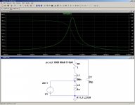
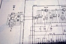
-In good quality tuners, there is normally a tuned circuit at the input, coupled to the main tuning control (cheaper receivers have a fixed, heavily damped tank circuit).
Such a circuit has the argument of the impedance equal to ~+90° or ~-90°.
Only at the resonant frequency is the impedance resistive, but it is a spot frequency.
If you make a random measurement, you'll see either + or - 90°.
See below
-Many tuners have an inductive matching component, balun or similar between the tuner and the antenna connector, and this inductive component will dominate the impedance
Attachments
Practical answer: It doesn't matter.
Losses in slightly mismatched antenna are very small and very easily made up for by front end gain.
A more or less close match does terminate the antenna cable system in its characteristic impedance which helps reduce common mode effects and reflected power in the cable.
Reflected power is a bit more problematic for transmitting where power transfer to the load is paramount but here the antenna is the generator and the receiver is the load. Although there is obviously power developed across the load, the front end is a voltage gain instrument. Power across a 75 ohm load with antenna signals is quite miniscule.
The impedance measurement you will get depends on the frequency you choose. Antennas work the same way. Move up or down a few mc and the picture will change.
...A ham since the 70s.
Thanks, that all does help. I didn't carefully tune to the measurement frequency (or vice versa) but will try that to see what happens. It makes sense that this is a voltage sensitive system, rather than a transmitter where we don't want to lose any radiated power, but it seems foolish to worry about carefully tuning an antenna and then connecting it to an unmatched load.
... my dad has been a ham for near forever, but it didn't rub off!
... my dad has been a ham for near forever, but it didn't rub off!
Most low-noise receiver inputs are a mismatch. This is because lowest noise does not coincide with highest signal. Sometimes people talk about a receiver input being power-matched (i.e. normal conjugate match for maximum power transfer) or noise-matched (lowest noise). For VHF and up noise-matching is normal, as external noise is low.
The impedance you measured will depend critically on the length of cable between your instrument and the receiver. The only time the cable length will not matter is if you have a perfect match, which is unlikely. To work out what the actual receiver impedance you would need to use a Smith chart.
(another radio amateur)
Interesting! It's counter intuitive, to me anyway, that max power and lowest noise wouldn't coincide. Now we're getting somewhere. Time to break out the Smith charts- it's been years since I messed with those, but I still have 'em. I have a nice working HP 4815 vector impedance meter to play with, without which I'd just be groping in the dark, he says, groping around in the dark.
Yeah!, it appears that there are several ham´s here. I´m LW1DSE, from Argentina.
Google Maps APRS
I never had an APRS station!!!
Google Maps APRS
I never had an APRS station!!!
Reducing noise by having a mismatch surprised me when I first heard of it, but having gone through the maths for one simple situation (here) I now understand it a little better. Some active devices benefit from a reactive input, so as well as an impedance mismatch the first tuned circuit might be slightly mistuned.
For broadcast MF and HF receivers low noise is not an issue as external noise is so high, so an impedance match is more likely.
For broadcast MF and HF receivers low noise is not an issue as external noise is so high, so an impedance match is more likely.
For broadcast MF and HF receivers low noise is not an issue as external noise is so high, so an impedance match is more likely.
Input impedance of HF receivers is actually all over the place, rarely 50 ohms even today. Most receivers have excess gain/sensitivity which removes this requirement on signal transfer grounds.
I suppose the important question is how mismatch affects s/n ratio not absolute signal level. A 3:1 impedance mismatch might not affect it much.
In any case, as you say, for HF, front end system noise figure is dwarfed by atmospheric noise and RFI from my neighbors cheap #@$#! plasma TV!
Similarly, broadcast FM signals are likely to be quite strong, so a dB or two of mismatch loss is immaterial when the signals are full quieting anyway.
Optimizing RX antenna matching seems to be of concern only at very high frequencies and challenging weak signal operations like space comms.
In my neighborhood, a strong signal RF environment is the big problem!
Fortunately, we can listen to jazz FM quite happily with a non-optimal system.
Broadcast FM signals may be strong for some people, but certainly not all. Assuming good AGC design (not always true!) then the level required for full quieting depends on front-end noise. Of course, good handling of strong signals is needed too for those nearer transmitters so like all other electronics a compromise may be needed.
I suppose some HF receivers still have too much gain, although professional ones should be OK - hopefully they are less subject to specmanship.
I suppose some HF receivers still have too much gain, although professional ones should be OK - hopefully they are less subject to specmanship.
This probably explains why, in my experience, there isn't much difference between FM antenna designs. The important factors are height and line of sight. Not that there aren't differences, but most of us have such sub-optimal installations (say, indoors) that the antenna design never performs as it should on paper.
Right now I'm trying to improve a receiver system in a machine shop. The metal building is near other metal buildings. I can't drill a hole to the outside. There is one wall of windows I'm going to try and work with, but my guess is the physical placement of the antenna will have far more to do with the result than matching, feedline or much of anything else.
Right now I'm trying to improve a receiver system in a machine shop. The metal building is near other metal buildings. I can't drill a hole to the outside. There is one wall of windows I'm going to try and work with, but my guess is the physical placement of the antenna will have far more to do with the result than matching, feedline or much of anything else.
That www is very good but its focused on HAM radio
This www is focused only on FM radio reception - EV's Best Top Rated FM and HD Radio Antenna Guide & Reviews
If anyone is interested I have just finished a few days playing with a balun on my Ron Smith Galaxy.
The Galaxy full wave loops are close to 75ohm so its tempting not to consider a balun. But the loop is balanced & 75ohm coax isn't, so at some frequencies the coax will be part of the antenna & current will exist in the coax shield. So I set about trying a coiled coax choke to isolate the antenna from the feeder. Its easy, the formula is simple, all you need is time & an "F" coupling kit, the hard part is DIY access if its on the roof.
Its made an already good antenna even better on my Naim NAT-05, no claims of sucking in remote stations, its all about SQ & stereo.
Only tempting for those who, unlike you, don't know what a balun actually does. Nothing to do with impedance matching, although some baluns can do that too.Mike B said:The Galaxy full wave loops are close to 75ohm so its tempting not to consider a balun.
Yes, that is what baluns are for. Sadly, many commercial FM antennas omit a balun. Until digital TV came along, many TV antennas did the same. Curiously, digital TV is more susceptible to interference than analogue TV even though EEs are always taught the opposite in class!But the loop is balanced & 75ohm coax isn't, so at some frequencies the coax will be part of the antenna & current will exist in the coax shield.
I've played with looped coax baluns a bit and that's todays project again. IMO, they're very fussy. A small change in dimensions has a huge effect on the tuning, so you either need a good recipe that's known to work, or some way to sweep or measure it. From reading the sites above, ferrites also work, but the coax balun is better.
Yes...Coax baluns are a lot fussier...and there is no simple observational way to know if they working well or not.
Ferrite core baluns are better in various ways, far more predictable and well-behaved. All sorts of troublesome couplings and resonances can exist in a coax coil balun...especially if you just wind up a messy overlapping coil. And you can't know the actual performance without appropriate test gear.
If snap-on ferrite cores are used it is a simple matter to add more on for a higher choking impedance. Target should be, say, 10x feedpoint impedance so two or three appropriate snap-ons would do the trick. 300-500 ohms per core is a good ballpark estimate.
You could also get a toroidal core and wind the coax through it a number of times.
Just make sure that the cores are effective in the frequency range of interest and you should be good to go.
A dipole, yagi, or any other balanced antenna won't work as well as it should without a balun.
PS: I'd beware of F connectors for open air use...they are not waterproof and water will easily wick into a braided shield coaxial cable and ruin it. If you have to use them use waterproofing putty or self-amalgamating silicone tape to seal the connection well.
I've played with looped coax baluns a bit and that's todays project again. IMO, they're very fussy. A small change in dimensions has a huge effect on the tuning, so you either need a good recipe that's known to work, or some way to sweep or measure it. From reading the sites above, ferrites also work, but the coax balun is better.
First off my thing is not a balun - yes I know that's what I called it - but it is a choke that is simply isolating the antenna from the feeder.
I researched this & found a ton of ways to "make" these coils. Ham radio www seems to be polluted with a lot of ways some very hit & miss & some way from any combo of logic/math/physics.
What I have done is to get the wire length right & make sure the coil has a self-resonance frequency (SRF) higher than the antenna/receiver operating range. If the SRF is lower thn the operating range the coil positively encourages the feed wire & antenna to work together.
The coil straight wire length should be just less than 1/4 wave length of the highest frequency the antenna is used for. 88-108MHz needs to be at or above 108MHz, this gives a wire length of 690mm (27.2 inches) The 1/4 wave wire length & the resulting number of turns sets the SRF higher than the operating frequency.
My 88-108MHz choke details:
Wire is Webro WF100 (foam dielectric & high 0.81 VF - not that VF is an issue with a coax choke)
690mm idealy has 3 turns of 73.3mm (2.88 inch) mean dia. (mean dia is the coax cable center to center) & a theoretical SRF of 119MHz.
Alternatives with this wire length - 2 turns gives 134MHz - 4 turns (too tight for the cable) gives 132MHz
Last edited:
Sounds like a choke balun to me, also known as a current-mode balun. In most cases better than a voltage-mode balun.
Amateur radio suffers from myths and stories (mainly to do with antennas and transmission lines), but not quite as much as audio! You might think that having to pass a technical exam to get a transmitting licence would ensure some level of technical knowledge but that is not always the case.
Amateur radio suffers from myths and stories (mainly to do with antennas and transmission lines), but not quite as much as audio! You might think that having to pass a technical exam to get a transmitting licence would ensure some level of technical knowledge but that is not always the case.
- Status
- This old topic is closed. If you want to reopen this topic, contact a moderator using the "Report Post" button.
- Home
- General Interest
- Everything Else
- Esoteric question on tuner inputs and RF design