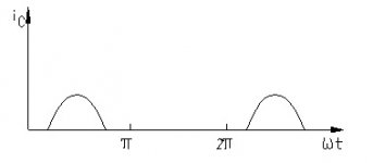
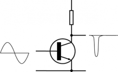
OK the first picture is an idealized representation, the second is true in the case of the common emitter amplifier shown, because the common emitter is an inverting amplifier.
Normally the collector resistor in the diagram would be replaced by an LC 'tank' circuit and the transistor would operate with a narrow conduction angle (<180 degrees).
The output (close to a sine wave) would be taken from the tank circuit either from a tap on the coil, by making the inductor a transformer, or by a split capacitor 'transformer' to provide a match to the next section, usually a filter.
Last edited:
Fig 1 says it is current. Fig 2 is presumably voltage, so they are both showing different aspects of the same thing.
Of course, silly me, it's widely known that a positive current flows when a negative voltage is applied.
Class C simply means the amplifying element is active <180° of the cycle. In audio, this supposes it happens twice / cycle, since there is no tuned circuit to reconstruct the missing half-cycle.
Class C can have uses in audio, when combined with something else: see Broskie's class A-C f.e.
Class C can have uses in audio, when combined with something else: see Broskie's class A-C f.e.
In audio, this supposes it happens twice / cycle
No. This would result in frequency doubling. Class C can be used in audio where the requirement for fidelity is very low, such as in a loudhailer.
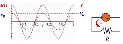
But isnt it ac voltage and current flow in the same phase when pass through resistor?which is as shown in figure below?sorry if i'm asking a stupid question.
View attachment 249457
Yes. DF96 is wrong, his reply is misleading. My second answer was sarcastic (a joke), I apologise for that. In the (class C) common emitter amplifier the transistor conducts when the voltage on the base is sufficiently positive. Current flows into the collector and the voltage at that point drops.
Last edited:
That simple single-transistor stage in fig 2 will invert the polarity of the signal. Regardless of class, the basic common emitter stage will always invert the polarity of the signal. Feed the output of the first stage through another similar stage and the circuit again inverts the waveform polarity, so two stages in sequence results in the original signal polarity. That is why in discussions of signal "phase" through an amp, yo hear mention of even number of stages versus odd number of stages.
The more positive the base is made, the more the transistor conducts. The more it conducts, the higher the current through the load resistor. And Ohm's Law tells us the more curent through the resistor, the more voltage across the resistor. The top end of that resistor is hopefully conected to the powr supply, so the voltage at that end stays the same. SO then increasing the voltage across the resistor must mean the bottom end of it - the collector of the transistor - will wind up at a lower voltage.
Forget polarity for a moment. Unless polarity was your only question. Look at fig 1. With a continuous sine wave into the class C amp, the resulting output is just those peaks. Now look at fig 2. With the continuous sine wave into the transistor, the output is just the peaks as well. Yes, they are now at opposite polarity, but the waveform is still only those peaks. The way it is drawn, those peaks are narrower looking than in fig 1, but the difference is the same as turning the horizontal sweep speed control on your scope. It only appears different.
Class C is not for audio. It is for RF. In the case of class C the output circuit "fills in" the missing space in the waveform, in effect an integrator... not a low distortion thing either, but effective for making things like an RF carrier...
_-_-bear
You're quite correct but if you want to get nit picky, the old Phase Linear 400 and 700 had outputs that technically were operating class C where class C is defined as the device conducting less than 180 degrees. The drivers operated class AB and started the outputs conducting slightly less than 180 degrees AKA class C.
G²
Forget polarity for a moment. Unless polarity was your only question. Look at fig 1. With a continuous sine wave into the class C amp, the resulting output is just those peaks. Now look at fig 2. With the continuous sine wave into the transistor, the output is just the peaks as well. Yes, they are now at opposite polarity, but the waveform is still only those peaks. The way it is drawn, those peaks are narrower looking than in fig 1, but the difference is the same as turning the horizontal sweep speed control on your scope. It only appears different.
all right.these makes sense about what happen to both of the output.now i'm clear about it.btw thanks everyone for the reply.
No, because each conducting period is of alternating polarity.No. This would result in frequency doubling.
If they are exactly symetrical, no second harmonic will be created.
I thought your reply was a bit strange. Apology accepted. I believe my answer is correct. The two graphs show collector current flow and voltage. Confusion may arise because the current graph rises from zero, while the voltage graph drops down from the supply rail. If you think of them as showing magnitude rather than absolute value then it doesn't matter if they 'ought' to be inverted.counter culture said:Yes. DF96 is wrong, his reply is misleading. My second answer was sarcastic (a joke), I apologise for that.
- Status
- This old topic is closed. If you want to reopen this topic, contact a moderator using the "Report Post" button.
- Home
- General Interest
- Everything Else
- what is the output of basic class C?


