Hello all, I've been working on designing and building my own optical compressor for a while and it'd been going quite well. I've now got a bit stuck on changing the design from feedforward to a feedback system, so that the response of the CdS cells can be linearised, with an aim to reduce distortion.
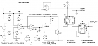
I had pictured this as a simple exercise but now I've come to actually implement it, I'm a little confused! I expect there's more than one way to do it but ultimately I don't want to have to change my existing design too much as it already gives good performance. Here's my design in SwCad, it misses the audio section as there are no facilities to use a CdS cell in the software, so only the sidechain and metering are shown:
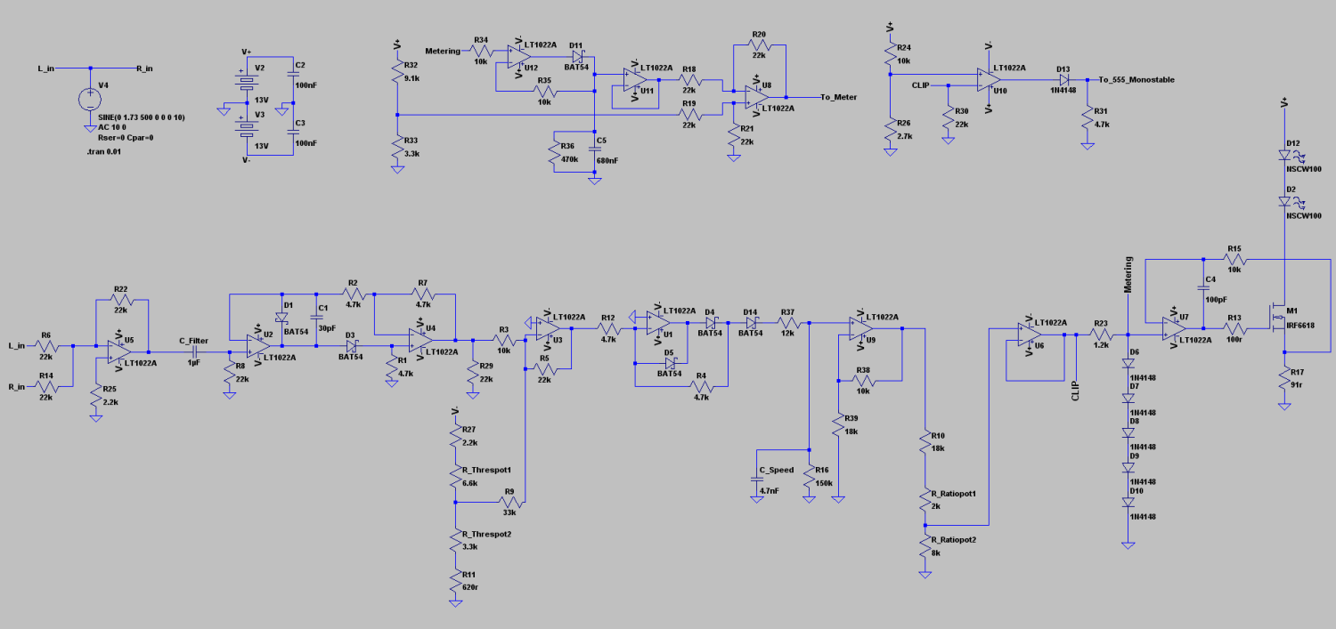
This exact circuit is built on breadboard and working fine (with LED current forced to 10uA or so min). The metering will naturally be changed to read from a second, matched, CdS cell and I'm confident about adding this. I had planned to also use this cell as a source of feedback for the sidechain to linearise the system, but looking at the LA4A (I had avoided looking at existing designs till now as I wanted to see what I came up with myself) I'm not sure how exactly the feedback is applied, but it appears to not use the metering cell to do it:
Urei LA 4 Schematic
Any thoughts on how this design is implementing feedback? How might I adapt it into my design or is there indeed a more simple way for me to do this using my second matched cell? My compressor is designed to offer some stereo functionality as a stereo bridge setup too btw, one sidechain is to be shared.
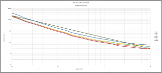
I include my testing results for CdS cells. I added a straight min to max line to show how the cell response doesn't quite follow this. This has been the case for all cells I've tested, they 'sag' in the middle, or possibly give more extreme values at the ends. Linearising should make them closer to the straight line, I think.
Any input appreciated!
I had pictured this as a simple exercise but now I've come to actually implement it, I'm a little confused! I expect there's more than one way to do it but ultimately I don't want to have to change my existing design too much as it already gives good performance. Here's my design in SwCad, it misses the audio section as there are no facilities to use a CdS cell in the software, so only the sidechain and metering are shown:
This exact circuit is built on breadboard and working fine (with LED current forced to 10uA or so min). The metering will naturally be changed to read from a second, matched, CdS cell and I'm confident about adding this. I had planned to also use this cell as a source of feedback for the sidechain to linearise the system, but looking at the LA4A (I had avoided looking at existing designs till now as I wanted to see what I came up with myself) I'm not sure how exactly the feedback is applied, but it appears to not use the metering cell to do it:
Urei LA 4 Schematic
Any thoughts on how this design is implementing feedback? How might I adapt it into my design or is there indeed a more simple way for me to do this using my second matched cell? My compressor is designed to offer some stereo functionality as a stereo bridge setup too btw, one sidechain is to be shared.
I include my testing results for CdS cells. I added a straight min to max line to show how the cell response doesn't quite follow this. This has been the case for all cells I've tested, they 'sag' in the middle, or possibly give more extreme values at the ends. Linearising should make them closer to the straight line, I think.
Any input appreciated!
Attachments
How are you using the CdS cells? Do they have LEDs paired with them?
I developed a circuit that linearizes an LDR, which is just an LED encapsulated with a CdS cell, to make a voltage-controllable resistor. I have it in SwCADIII (LTSpice). I do have LTSpice models of LDRs. The linearizing circuit was not really trivial, even assuming matched LDRs. My circuit is actually just a voltage-controlled resistance, with linear resistance response of 200k Ohms per volt from about 500 Ohms to 1 Meg Ohm. It takes about 0.5 seconds worst case to go from one commanded resistance to another. So it might not be useful to you.
Now that I look at it, it is probably WAY too complicated, since it results in "perfect" linearization, which wouldn't be perfect in practice even if you used two perfectly-matched LDRs.
But there should be at least two other ways to do it:
One idea is that the result of placing a mathematical function in the feedback loop of a noninverting opamp circuit is that the output becomes the inverse mathematical function. So then you should be able to cancel one with the other, or, linearize? I haven't tried this type of thing, much, and it was years ago.
A much simpler idea would be to use an "exponential function" circuit to sum with the LDR control curent, to remove the logarithmic nature of the LDR response curve (since log and exp are inverse functions of each other). Just scale the exponential response until it best-cancels the non-linearity of your sort-of-logarithmic CdS curve. I think there are exp and log circuits in AN-20 and AN-31 at national.com.
So let's see... If you have an LDR with a resistor in series with the LED, then it would basically be voltage-controlled instead of current-controlled. If you put that same voltage on the input of an opamp that had the CdS cell of another (matchd) LDR in its feedback loop, and the same value resistance in series with its LED, to which you also applied the input voltage, and then you summed the opamp's output voltage with the first LDR's original control voltage... what would happen? I'll go try it.
There is a little more about all of those in this thread:
http://www.diyaudio.com/forums/analog-line-level/170381-precision-led-ldr-based-attenuator-6.html
Tom
Thanks for your reply! Uncovered lots of interesting stuff ")
Yep, my LDRs are paired with high output green LEDs to produce those curves.
Your linearising circuit sounds interesting, I saw mention of it in the thread you linked. It may be overly complex, absolute accuracy is not essential here since even with no linearisation distortion only becomes very noticeable with relatively high gain reduction and certain source material. Of course adding attack and release time cuts it out too, but I'd like to option of fast limiting/natural response and high compression. Perhaps we can simplify the circuit for this relatively crude application?
The exponent function in the control/sidechain is a really attractive solution as it avoids feedback and possible issues of altering the timing control function that feedback could bring. It won't give a perfect linear response, but far more linear than what I have measured now, which is indeed very close to log. I don't give the cells total darkness like people making volume controls will, as this greatly slows their reponse when a transient comes back in. I give the LED a minimum current of around 10uA, this still leaves me plenty of dynamic range for this application and as a consequence I suspect the cell response is closer to log than if it were taken to absolute darkness.
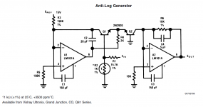
Anyhow, I think I've found the correct circuit from AN-31:

So I can imagine placing this after all the threshold, attack/release timing circuits and in no way affecting their functionality, which is nice. It'd take some effort to adjust the reponse to be a 'line of best fit' when related to my response graphs but I can be done. I'd probably forego the matched transistor pair and tempco resistor as absolute accuracy is not achievable anyhow. Some distortion may be left, but hopefully it'll just be musical/valve like non-linearity.
As much as I like that solution, I suspect that what you are describing in your last paragraph is actually simpler? I can't quite get to a schematic from the description, if you have any drawn I'd be very keen to see them! It sounds like it could be implemented around the LED drive (VCCS) in my circuit and thus be an ideal solution for me. The graphs were created to match CdS cells for this purpose, CdS 6 and CdS 2 make a nice pair and hopefully I could drive the meter from this feedback cell too.
Thanks again and any further guidance is much appreciated! This seems to be an area you've researched quite extensively so I'm keen to learn from your knowledge
Yep, my LDRs are paired with high output green LEDs to produce those curves.
Your linearising circuit sounds interesting, I saw mention of it in the thread you linked. It may be overly complex, absolute accuracy is not essential here since even with no linearisation distortion only becomes very noticeable with relatively high gain reduction and certain source material. Of course adding attack and release time cuts it out too, but I'd like to option of fast limiting/natural response and high compression. Perhaps we can simplify the circuit for this relatively crude application?
The exponent function in the control/sidechain is a really attractive solution as it avoids feedback and possible issues of altering the timing control function that feedback could bring. It won't give a perfect linear response, but far more linear than what I have measured now, which is indeed very close to log. I don't give the cells total darkness like people making volume controls will, as this greatly slows their reponse when a transient comes back in. I give the LED a minimum current of around 10uA, this still leaves me plenty of dynamic range for this application and as a consequence I suspect the cell response is closer to log than if it were taken to absolute darkness.
Anyhow, I think I've found the correct circuit from AN-31:
So I can imagine placing this after all the threshold, attack/release timing circuits and in no way affecting their functionality, which is nice. It'd take some effort to adjust the reponse to be a 'line of best fit' when related to my response graphs but I can be done. I'd probably forego the matched transistor pair and tempco resistor as absolute accuracy is not achievable anyhow. Some distortion may be left, but hopefully it'll just be musical/valve like non-linearity.
As much as I like that solution, I suspect that what you are describing in your last paragraph is actually simpler? I can't quite get to a schematic from the description, if you have any drawn I'd be very keen to see them! It sounds like it could be implemented around the LED drive (VCCS) in my circuit and thus be an ideal solution for me. The graphs were created to match CdS cells for this purpose, CdS 6 and CdS 2 make a nice pair and hopefully I could drive the meter from this feedback cell too.
Thanks again and any further guidance is much appreciated! This seems to be an area you've researched quite extensively so I'm keen to learn from your knowledge
Attachments
I went back through my old stuff and found one of my first versions, which is quite simple. The schematic shown uses a linearized LDR to create a voltage-controlled resistor that responds linearly, at about 200k per volt, from something like .05 Volt to 5 Volts.
Attachments
I have uploaded the LTSpice files for the LDR in a zip file, and the schematic in a .txt file. For the schematic, just rename the file without the .txt extension. Unzip the zip file and put the files in the same folder as the .asc file containing the schematic.
Go to the tools icon and select the Spice tab and specify the Alternate Solver.
Have fun!
P.S. You can plot the resistance of the LDR by first plotting the voltage and then right-clicking on the voltage's name in the plot heading and changing the plot expression by adding /I(I2), to divide by the current from the current source that's in that version.
P.P.S. I forgot to mention that I was messing around with the capacitor values. They could probably be much smaller, in a real circuit (or in the sim if you don't use infinitely-steep edges when switching the control signal, like I did).
Attachments
Last edited:
Thanks for the schematic and vactrol model, it's working in my SwitcherCAD. It looks fairly simple, part of the circuit is a VCCS, which my design already uses, so the only new part is U2, which appears to me to be some sort of difference amplifier? Control voltage minus the feedback voltage?
I just can't quite get my head around how to implement it in my design, I think building it for real in this case will make a bit more sense to me, I have matched vactrols to hand. I'm not even quite sure what I should be seeing I guess, until it's fully implemented and then a reduction in distortion when using fast compression speed settings should be observable/audible.
Is this concept the same as the schematic you posted? It sounds a little different to me, perhaps easier to implement.
I tried the anti-log circuit in CAD and I'm not so optimistic for that route now. It's not the neatest circuit, it has a lot of quirks that need working out!
I just can't quite get my head around how to implement it in my design, I think building it for real in this case will make a bit more sense to me, I have matched vactrols to hand. I'm not even quite sure what I should be seeing I guess, until it's fully implemented and then a reduction in distortion when using fast compression speed settings should be observable/audible.
So let's see... If you have an LDR with a resistor in series with the LED, then it would basically be voltage-controlled instead of current-controlled. If you put that same voltage on the input of an opamp that had the CdS cell of another (matchd) LDR in its feedback loop, and the same value resistance in series with its LED, to which you also applied the input voltage, and then you summed the opamp's output voltage with the first LDR's original control voltage... what would happen? I'll go try it.
Is this concept the same as the schematic you posted? It sounds a little different to me, perhaps easier to implement.
I tried the anti-log circuit in CAD and I'm not so optimistic for that route now. It's not the neatest circuit, it has a lot of quirks that need working out!
The linearization circuit I gave is actually not from the description you quoted from my earlier message.
My circuit just responds to the input voltage, to set the resistance of the bottom vactrol. Modify the voltage source (or disconnect it and use a different one) to be a plain DC voltage, between 0 and 5 Volts. Run (plotting the voltage at the top terminal on the right side of the bottom vactrol) for a few seconds, until it's stopped changing. Plot the resistance across the two R terminals of the bottom Vactrol, by plotting the voltage of the top terminal and then, after it's stopped, right-clicking on the voltage's heading above the plot and changing the expression that's plotted by adding /I(I2) after the voltage heading. That should give Ohms on the vetical axis. Trying different control voltages, you should see that the resistance changes perfectly-linearly versus the control voltage, at about a constant 200k Ohms per volt. (Note too that there is a constant 5 microamp current souce needed. I have a simple circuit for that. Also note that I have not built any of this.
That circuit might not be exactly what you're needing but the linearization circuit could be modified for different types of applications.
Regarding the anti-log circuit you posted. It looks a bit cantankerous. I have played with analog multiplier circuits and they can be a bit difficult, in spice. They use very similar types of circuits.
I would try the "Exponential output" circuit, near the botom of the page at
Operational amplifier applications - Wikipedia, the free encyclopedia .
It's just a single diode with one opamp and one resistor. You should be able to add an opamp or two and maybe a voltage or current source and scale the output to be where you need it.
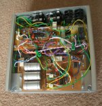
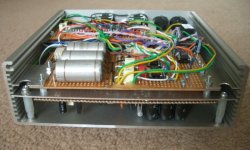
Thanks for your help on this. Annoyingly, I had to get this project moving along as I'm soon going back to Uni where I won't be able to work on this. As such I preceeded with the design as feedforward/non-linearised. I found that actually, despite the non-linearity of the cells, that distortion wouldn't manifest provided the control circuit was slowed down slightly as you would typically do in a compressor.
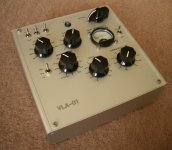
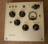
Here's the finished article, thought it may be of some interest!

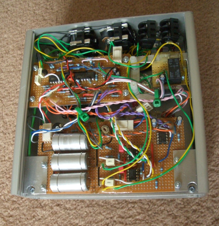
On the speed dial I included a 'natural' setting, which means the control circuit is not slowed at all. This can be useful for some things but you will hear distortion with certain material on this setting. The switch has 12th, 3rd or lim settings, which are the corresponding attack times (ie, in 3rd with the speed set for 30ms, the attack is 10ms and release 30ms). Lim (limiter) is 'instant' attack.
I should have a demo video up soon so it can be heard
Here's the finished article, thought it may be of some interest!
On the speed dial I included a 'natural' setting, which means the control circuit is not slowed at all. This can be useful for some things but you will hear distortion with certain material on this setting. The switch has 12th, 3rd or lim settings, which are the corresponding attack times (ie, in 3rd with the speed set for 30ms, the attack is 10ms and release 30ms). Lim (limiter) is 'instant' attack.
I should have a demo video up soon so it can be heard
Attachments
- Status
- This old topic is closed. If you want to reopen this topic, contact a moderator using the "Report Post" button.
- Home
- General Interest
- Everything Else
- Applying linearising feedback to optical compressor