Bateman used to have the cable articles on his website which is gone now.
Using the "Internet Wayback Machine" I found this:
Capacitor Sounds, Speaker Cables and Crossover Inductors.
Using the "Internet Wayback Machine" I found this:
Capacitor Sounds, Speaker Cables and Crossover Inductors.
Your model results do not support this within the audio band..In fact, that is not even the case for audio: for most cables, most of the audio spectrum will be well below the LF cut off frequency, meaning the amplifier will see a reactive load of up to -45°
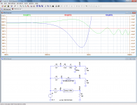
To put things in perspective, here is the comparison between three 40m cable models feeding a 8Ω purely resistive load. The cable has a characteristic impedance of 100Ω.
The impedance seen by the amplifier is plotted from 1KHz to 100KHz (below 1KHz nothing interesting happens) for an actual cable (green), an ideal transmission line having no LF effects (red), and a lumped model (blue).
Despite the 40m length, the effects remain relatively small, but it is interesting to note that the crude lumped model does better than the ideal transmission line, particularly regarding phase (dotted lines).
Next are the same parameters viewed with Nyquist. The markers are at 20KHz.
And finally, the frequency response seen by the speaker (the amplitude of the red trace has been scaled to more or less match the other traces)
Why did you use a series resistance of 7.5 ohms in the lumped model?? Did you mean to use .0075?
I recommend you review your model. In addition, read Cyril where he details why he required 200 lumped elements to bring his model closer to reality. Using one LR and C is not consistent with actual results.
Bateman used to have the cable articles on his website which is gone now.
Using the "Internet Wayback Machine" I found this:
Capacitor Sounds, Speaker Cables and Crossover Inductors.
I do appreciate the effort you and speedskater are using to bring the information on forum. All his articles are very good (albeit technically challenging for many to follow). I had been told he had some health issues, I hope all is well with him.
cheers, jn
Here again, because the characteristic impedance is an iterative impedance, not a regular one that you can measure with a standard impedance-meter.Your model results do not support this within the audio band..
However, if the line has an infinite length, the apparent impedance becomes the characteristic impedance.
Below is an example of "infinite" line: 200 segments of 320m are cascaded, giving a good approximation of infinity down to 100Hz.
The total is left unterminated, because it doesn't really matter: the return signal is vanishingly low
No, it is actually 7.5Ω, because the cable modelled is 0.5mm twisted pair.Why did you use a series resistance of 7.5 ohms in the lumped model?? Did you mean to use .0075?
These are models I had available, because I created them for my work and they would require a lot of work to be adapted for other cables.
The lossy model exactly mirrors the reality: it is not based on lumped elements, and is completely accurate at any frequency.I recommend you review your model. In addition, read Cyril where he details why he required 200 lumped elements to bring his model closer to reality. Using one LR and C is not consistent with actual results.
I have included the (very) crude lumped element model in the previous sim to show that at audio frequencies, it performs rather well, better anyway than an ideal transmission line model
Attachments
Here again, because the characteristic impedance is an iterative impedance, not a regular one that you can measure with a standard impedance-meter.
However, if the line has an infinite length, the apparent impedance becomes the characteristic impedance.
As I said, we're speaking about short speaker wire lengths terminated terribly.
Below is an example of "infinite" line: 200 segments of 320m are cascaded, giving a good approximation of infinity down to 100Hz.
The total is left unterminated, because it doesn't really matter: the return signal is vanishingly low
When I said 200 segments, I meant 200 to model the length given, in Cyril's case it was 4.9 meters.
No, it is actually 7.5Ω, because the cable modelled is 0.5mm twisted pair.These are models I had available, because I created them for my work and they would require a lot of work to be adapted for other cables.
Ah, 24 guage, 40 meters long. Not exactly appropriate for the discussion, eh?
It's important to model what is being discussed rather than trying to shoehorn the available model to different circumstances. You're losing HALF the power to the line, certainly not reality..
The lumped element model NEEDS sufficient elements to make the t-line model match the lumped element as well as match real hardware results. This is precisely what Cyril Batemen did, and where the 200 elements came from.The lossy model exactly mirrors the reality: it is not based on lumped elements, and is completely accurate at any frequency.
I have included the (very) crude lumped element model in the previous sim to show that at audio frequencies, it performs rather well, better anyway than an ideal transmission line model
Despite all this discussion, what is being bypassed it the fact that ACTUAL hard measurements of load to line discontinuity caused reflections has been demonstrated despite statements that the line is too short at these frequencies.
Also, if you were to actually put 40 meters of zip into an 8 ohm load, the reflection at the source will be delayed 100 microseconds.. Note that the actual load current will be one prop delay in front of that, roughly 120 nanoseconds earlier...99.88 uSec delayed. That delay is not inconsequential to humans.
jn
Last edited:
We seem to be once again co-mingling in-band and out-of-band transmission line characteristics. Of course a speaker cable does not have a single characteristic impedance. At low frequencies it's impedance is near infinite and only approaches it's advertised value near 100KHz.
Cyril Bateman Articles
Electronics World Magazine
Measuring Speaker Cables: 1 Cyril Bateman Dec 1996 p925
Measuring Speaker Cables: 2 Cyril Bateman Jan 1997 p52
Measuring Speaker Cables: 3 Cyril Bateman Feb 1997 p119
Understood, Kevin, but as I discussed in my book, the out-of-band transmission line effects of speaker cable can affect amplifier stability, and that will affect the sound.
Cheers,
Bob
Understood, Kevin, but as I discussed in my book, the out-of-band transmission line effects of speaker cable can affect amplifier stability, and that will affect the sound.
Cheers,
Bob
Where do you typically like to put open loop unity gain?
jn
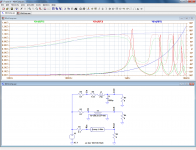
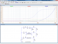
To put things in perspective, here is the comparison between three 40m cable models feeding a 8Ω purely resistive load. The cable has a characteristic impedance of 100Ω.
The impedance seen by the amplifier is plotted from 1KHz to 100KHz (below 1KHz nothing interesting happens) for an actual cable (green), an ideal transmission line having no LF effects (red), and a lumped model (blue).
Despite the 40m length, the effects remain relatively small, but it is interesting to note that the crude lumped model does better than the ideal transmission line, particularly regarding phase (dotted lines).
Next are the same parameters viewed with Nyquist. The markers are at 20KHz.
And finally, the frequency response seen by the speaker (the amplitude of the red trace has been scaled to more or less match the other traces)
Good work, Elvee. However, it would be even more interesting if you plotted it out to 10MHz. A lot of the fun does not begin until beyond 100kHz.
With plots to 10MHz, it would also be interesting to see these three situations depicted for the conditions of the cable terminated in 100 ohms, the cable terminated into a short, and the cable completely unterminated.
I did that for a 10-foot length of Zip-type Monster cable in Figure 18.4 in my book "Designing Audio Power Amplifiers".
It gets REALLY ugly between 10MHz and 100MHz in the mis-terminated cases. While this is well above the ULGF of most amplifiers, it is not necessarily well above the frequency range where some amplifier output stages can be prone to local parasitic osillation, especially if fast output transistors are used and/or no output L-R isolating network is used.
On the other hand, even ordinary speaker cable terminated in 120 ohms was remakably well-behaved out to 80MHz. A Zobel at the loudspeaker end consisting of a 0.01uF capacitor in series with 120 ohms is all it takes.
I have long believed that some of the audible differences between amplifiers that are not accounted for with the usual lab tests are due to amplifier misbehavior in the real world, such as instability provoked by speaker cables and loudspeaker loads.
Cheers,
Bob
Where do you typically like to put open loop unity gain?
jn
I put ULGF between 500kHz and 2MHz, most of the time at 1MHz.
Cheers,
Bob
Good work, Elvee.
I concur.
On the other hand, even ordinary speaker cable terminated in 120 ohms was remakably well-behaved out to 80MHz. A Zobel at the loudspeaker end consisting of a 0.01uF capacitor in series with 120 ohms is all it takes.
And for those who like low impedance cables, match the resistor to it's hf Z as well.
We agree.I have long believed that some of the audible differences between amplifiers that are not accounted for with the usual lab tests are due to amplifier misbehavior in the real world, such as instability provoked by speaker cables and loudspeaker loads.
Cheers,
Bob
I also consider the group delay caused by the speaker cable driving a very low Z load, as at low frequency the cable Z rises a lot, it's intrinsic vprop slows, and the resultant group delay rises into human threshold areas, especially within the 500 to 2K midband.
Ah, thanks.I put ULGF between 500kHz and 2MHz, most of the time at 1MHz.
Cheers,
Bob
Have you any interest in measuring mismatched short line delays?
jn
I concur.
And for those who like low impedance cables, match the resistor to it's hf Z as well.
We agree.
I also consider the group delay caused by the speaker cable driving a very low Z load, as at low frequency the cable Z rises a lot, it's intrinsic vprop slows, and the resultant group delay rises into human threshold areas, especially within the 500 to 2K midband.
Ah, thanks.
Have you any interest in measuring mismatched short line delays?
jn
How short?
But I probably don't have the time right now.
If I did it, I'm guessing I would do it for sinusoids of different frequencies using 2 channels of my Agilent 8 Gs/s DSO, which has a horizontal sweep down to 100 ps/div. I would compare the delays of the sinusoids at each end of the cable after calibrating out any residual scope channel delay mismatch. The test cable would be configured in an out-and-back loop so that the same-length probes could be used for measurement at both ends. The loop would have to be configured as large as possible in diameter to minimize any possible crosstalk between different locations along the cable.
Does that seem like a good way to do the measurement you are thinking of?
One could also do it with square waves or very short pulses, but I don't think that would reveal the frequency depedence you seek (but would subjectively reveal time dispersion incurred in the cable).
Cheers,
Bob
The main issue is capturing the delay of say, a 500hz sine at zero crossing down to the microsecond level.How short?
But I probably don't have the time right now.
If I did it, I'm guessing I would do it for sinusoids of different frequencies using 2 channels of my Agilent 8 Gs/s DSO, which has a horizontal sweep down to 100 ps/div. I would compare the delays of the sinusoids at each end of the cable after calibrating out any residual scope channel delay mismatch. The test cable would be configured in an out-and-back loop so that the same-length probes could be used for measurement at both ends. The loop would have to be configured as large as possible in diameter to minimize any possible crosstalk between different locations along the cable.
Does that seem like a good way to do the measurement you are thinking of?
One could also do it with square waves or very short pulses, but I don't think that would reveal the frequency depedence you seek (but would subjectively reveal time dispersion incurred in the cable).
Cheers,
Bob
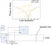
Unfortunately, my computer with the drawings is currently doa. The test setup is to drive the zip cable using a low z out amp, 15 or 20 feet of cable, to a varying load resistance far end. At the amp, use a .1 ohm current viewing resistor inserted into the ground so that you can measure the cable's current without messing the test up too much.
By varying the end load at a constant frequency, you can see the delay caused by the line slowly (relatively speaking) filling up due to transit delays and end reflections. This will show the minima which occurs when line equals load, and the cusp behavior on either side of match. Trying to see the one transit delay at match is doomed from the start, unless you have differential ins. I wrestled with that for a while, and had to settle with looking at the current at the amp, knowing that it was at most, one transit delay removed from the load current.
Using a square wave would certainly show the settling time of the cable/load system, but yes, the information while interesting, might not be very applicable.
I'll try to find the pics elsewhere in the meantime..
Bingo...found it..
jn
Attachments
Last edited:
a PC soundcard would be fine for 500 Hz, 1 us phase resolution
I'm afraid single digit resolution isn't good enough. I suspect 10 or 100 nSec resolution would be best.
Cyril demonstrated 10 uSec at 10Khz with a 4.9 meter cable and a VSWR of 2.2:1 at that frequency.
Not everybody has an rf bridge available... and the results as he demonstrated, don't exactly show us what is occurring. Yes, there is a reflection of the 10 KHz signal, yes it's 50 times slower than the cable prop delay, but how does that impact what we hear?
My test is designed to see the actual load current albeit one prop delay away, to be able to later test actual speaker loads. My interest lies in being able to spot the impedance changes caused by eddies of the coil as well as eddies caused by the coil movement in the field. Velocity dependence of the coil's effective resistance (Rs).
The results are to determine the line to load match boundaries necessary to limit group delay of all frequencies during actual music.
jn
for a crude heruistic - a second gets you ~1000 zero crossing to average for sub sample time resolution of 500 Hz sine phase
you can use extended observation time, high dynamic range to obtain extremely high time resoluiton
FFT does exactly the right thing in calulating the phase with the complex value
you can use extended observation time, high dynamic range to obtain extremely high time resoluiton
FFT does exactly the right thing in calulating the phase with the complex value
for a crude heruistic - a second gets you ~1000 zero crossing to average for sub sample time resolution of 500 Hz sine phase
you can use extended observation time, high dynamic range to obtain extremely high time resoluiton
FFT does exactly the right thing in calulating the phase with the complex value
Sounds good. But it's beyond my abilities. I'm a simple country doctor, Jim..
It also allows the storage of say, a 50 hz response for later subtraction of a two tone signal used to measure velocity dependence of a speaker's Rs.
I really do like your suggestion..
jn
its really not as hard as improvising a laser to cut your way out of a jail cell...
Audacity lets you play your test waveforms and record, if you don't like any math SW then LTspice imports .wav, can cruise the FFT with the cursors to get the relative amplitude, phases of any 2 bins
some soundcard freeware like Visual Analyzer may have the capability too - some already know how to calculate complex impedance
...just don't step into the transporter wearing a Red Shirt
You do test my memory. Don't I need a communicator for that??its really not as hard as improvising a laser to cut your way out of a jail cell...
Audacity lets you play your test waveforms and record, if you don't like any math SW then LTspice imports .wav, can cruise the FFT with the cursors to get the relative amplitude, phases of any 2 bins
some soundcard freeware like Visual Analyzer may have the capability too - some already know how to calculate complex impedance
I'd really just like to see the amplitudes. if I want to see imaginary, I'll buy a Q chip..
They're always the ones to bite the big one, aren't they?...just don't step into the transporter wearing a Red Shirt
jn
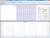
I am perfectly aware of that. This was just to answer your question about the 45° phase missing at low frequencies.As I said, we're speaking about short speaker wire lengths terminated terribly.
Note that having a complex and variable characteristic impedance is not without consequences, even for short lengths: these effects will alter the impedance seen by the amplifier
Yes, the 200 number I took is just a coincidence.When I said 200 segments, I meant 200 to model the length given, in Cyril's case it was 4.9 meters.
Anyway, as I said in another discussion, modelling real lines with lumped elements, even in very large numbers is a poor and crude method.
For physical simulation, it might still be acceptable but for soft simulation there are better options
Not appropriate if we want to discuss specific numerical results, but perfectly adequate to illustrate theoretical concepts like the variation of characteristic impedance with frequency.Ah, 24 guage, 40 meters long. Not exactly appropriate for the discussion, eh?
It's important to model what is being discussed rather than trying to shoehorn the available model to different circumstances. You're losing HALF the power to the line, certainly not reality..
My point is that the usual transmission line concepts like matching, etc, are essentially useless at audio frequencies.
If you build a 8Ω speaker cable, it will stay at that value down to a few KHz, at the very best, and go all over the place below: matching makes no sense, you would need to present a load having a phase of 45° over many octaves, together with a variable magnitude, which is completely unrealistic
Transmission line effects are completely agnostic, and manifest themselves wheter the line is 1,000λ or 0.001λ. The underlying theory remains the same.Despite all this discussion, what is being bypassed it the fact that ACTUAL hard measurements of load to line discontinuity caused reflections has been demonstrated despite statements that the line is too short at these frequencies.
With a good VNA working in virtual time-domain, you can see incredibly small details.
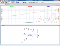
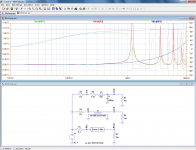
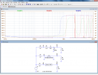
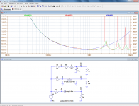
Here you are. I have also included a 20Ω load, partly to adress John's criticism about the lack of suitability of the 0.5mm model, and partly to get a more realistic view of the problem: actual speaker cables normally have an impedance lower than 100Ω, and with 20Ω, the Zo to Zl ratio is better respected.Good work, Elvee. However, it would be even more interesting if you plotted it out to 10MHz. A lot of the fun does not begin until beyond 100kHz.
With plots to 10MHz, it would also be interesting to see these three situations depicted for the conditions of the cable terminated in 100 ohms, the cable terminated into a short, and the cable completely unterminated.
The 100Ω case is duplicated, to zoom on the finer details.
This discussion can be of interest too:
http://www.diyaudio.com/forums/parts/226855-modelling-audio-cables-4.html#post3309063
Attachments
Last edited:
I am perfectly aware of that. This was just to answer your question about the 45° phase missing at low frequencies.
Note that having a complex and variable characteristic impedance is not without consequences, even for short lengths: these effects will alter the impedance seen by the amplifier
Yes, the 200 number I took is just a coincidence.
Anyway, as I said in another discussion, modelling real lines with lumped elements, even in very large numbers is a poor and crude method.
For physical simulation, it might still be acceptable but for soft simulation there are better options
Not appropriate if we want to discuss specific numerical results, but perfectly adequate to illustrate theoretical concepts like the variation of characteristic impedance with frequency.
My point is that the usual transmission line concepts like matching, etc, are essentially useless at audio frequencies.
If you build a 8Ω speaker cable, it will stay at that value down to a few KHz, at the very best, and go all over the place below: matching makes no sense, you would need to present a load having a phase of 45° over many octaves, together with a variable magnitude, which is completely unrealistic
Transmission line effects are completely agnostic, and manifest themselves wheter the line is 1,000λ or 0.001λ. The underlying theory remains the same.
With a good VNA working in virtual time-domain, you can see incredibly small details.
Here you are. I have also included a 20Ω load, partly to adress John's criticism about the lack of suitability of the 0.5mm model, and partly to get a more realistic view of the problem: actual speaker cables normally have an impedance lower than 100Ω, and with 20Ω, the Zo to Zl ratio is better respected.
The 100Ω case is duplicated, to zoom on the finer details.
This discussion can be of interest too:
http://www.diyaudio.com/forums/parts/226855-modelling-audio-cables-4.html#post3309063
Hi Elvee,
Thank you very much!
It may take me awhile to get this all looked at as we are celebrating Independence Day here in the US.
Cheers,
Bob
- Status
- Not open for further replies.
- Home
- General Interest
- Everything Else
- speaker cable myths and facts