Two wideband dipoles suitable phased would do the trick.
How are you proposing to achieve a suitable phase relationship across a 4:1 range of frequencies?
2C39A and 3CX100A have gain to >1GHz. 3GHz I think.
w
but do you really need an amp?
I'm thinking two amps!
Obviously two coat hangers is not a fully optimized antenna system, but it performs far better than expected. Many $50 to $100 antennas on the market aren't either. Many of them are amplified, again with a less than optimum amplifier. So I will experiment with amps just for a learning experience. I have been building ham radio amps for years, and I design two way radio equipment at work. So, the next step is amplification. Down the road, I'm looking at a ultra cheap rhombic antenna. I built one about 15 years ago for the 902 MHz ham band and it worked quite well for TV even picking up VHF channel 3 (63 MHz) from Tampa occasionally, about 200 miles away.
Why two amps?
The spectrum analyzer reveals several signals just above the noise floor. I have maybe 10 db of cable loss at the high frequencies, which adds directly to the system noise figure. I know my old spectrum analyzer has a noise figure of at least 10 db probably worse. I don't know what the noise figure of a modern TV is. Putting an amplifier at the antenna with a noise figure of 1 db and sufficient gain will do wonders to lower the system noise figure. This amp needs a low noise figure, good gain, and good intermod performance. I may put the rhombic on a rotor and use it for ham radio and general snooping, so frequency response out to 1.3 GHz would be nice. I am looking at the SPF-5122Z from RFMD (under $5 at Digikey) and the HMC617LP3 from Hittite Microwave (hard to get).
I have been using a Radio Shack amplified splitter to drive long cables (over 100 feet) to TV's throughout the house, and a pair of ethernet TV tuners. The analyzer revealed that the current amp cuts off several channels above 650 MHz and has severe gain tilt, so it must go. I am currently driving 4 seperate cables from its outputs, and some of them have multiple resistive splitters at the far ends. The amp here needs outstanding intermod performance, good power output capability, reasonable noise figure, and frequency response to 1.3 GHz. The Avago MGA-30689 is the winner here. I have already been pounding these with LTE signals from 700 MHz to 2.4 GHz, at +20 dbm peak power. LTE demands linearity, and more linearity, and flat frequency response across a 20 MHz channel.
Thanks George!....now the girls can watch all their soaps in the break room
And you will be found responsible for the loss of productivity. The plant where I work has a large international population. The computer network got overloaded during the World Cup because everybody was watching the games on their desk computers. They finally put the games on in the break rooms, the gym, and the lobby.
I believe TV receivers are required to have a NF of 14dB for sale in the US. Certainly many manufacturers no longer strive to achieve performances in line with those sought in the past, signal conditions being generally better than they were and many receivers being fed from satellite receivers or other set-top boxed or players.
A MMIC with a NF of 1dB is certainly excellent, but one of the widely available devices with 3dB NF is probably perfectly adequate at the masthead. Minicircuits have the PHA-11+ with very good intermod and 75 ohm match, but this is a recent introduction, and I can't find anywhere to buy it yet.
w
A MMIC with a NF of 1dB is certainly excellent, but one of the widely available devices with 3dB NF is probably perfectly adequate at the masthead. Minicircuits have the PHA-11+ with very good intermod and 75 ohm match, but this is a recent introduction, and I can't find anywhere to buy it yet.
w
Execelent work I used to love building my own antenna's when I lived in naples.
I never ever bought a commercial one when I was playing around in the 11 meter band and I would blow away most antron 99 setups with a 3/4 wave ground plane.
Thanks for this interesting read. jer
I never ever bought a commercial one when I was playing around in the 11 meter band and I would blow away most antron 99 setups with a 3/4 wave ground plane.
Thanks for this interesting read. jer
Two equal lengths of cable? Impedance matching is the difficult part. How about a two-input preamp, with signal combining at the output?wakibaki said:How are you proposing to achieve a suitable phase relationship across a 4:1 range of frequencies?
Two equal lengths of cable?
The problem is the high angle radiation, which is most of the radiation for a horizontal dipole. You can stack cophased horizontal dipoles vertically and improve the vertical firing angle and the high angle lobes, but the performance is spacing and height above ground dependent and consequently variable with frequency. I think with fixed spacing you'd want to be able to alter the phase relationships between the dipoles, and keep the spacing under a wavelength even at the highest frequency of interest. You could rack them for spacing, but it's not a simple arrangement then. A sufficiently broadband dipole will be a biconical which offers constraints on spacing anyway.
Radio Antenna Engineering - Design of a Horizontal Half-wave-dipole Antenna System
w
Unknown to me the guy across the street went to Best Buy last weekend to buy a TV antenna. He got a silver plastic box about 6 inches by 8 inches and 1 inch thick, made by Philips. It cost about $40 and according to the instructions has "18 db of gain". It plugs into the wall so it has an amp. The salesman told him that it would work OK but the box clearly says UHF only.
He mounted it on a pole at about the same height as my antenna. His antenna does receive the two VHF channels and most of the Miami based UHF channels. It only gets some of the West Palm Beach channels. Time for some wire hangers....
I started the layout for the mast head amp. The board will be capable of using the RFMD SPF-5122Z or the Avago MGA-633P8. Both are stocked at Digikey. Tiny little SMD creatures though.
Only when it is near the ground. A UHF TV antenna is likely to be sufficiently high (in terms of wavelengths) to be virtually in free space. Also, the ground will be lossy so a poor reflector.wakibaki said:The problem is the high angle radiation, which is most of the radiation for a horizontal dipole.
I accept that vertical spacing of biconical antennas may be a problem. There is an interesting variant: a stacked/phased DIY bowtie TV antenna (see Google). This uses 4 bowties.
Commercial bowties have been around since the 1950's, probably older but that's how far back my memory reaches.
Looking back into my memory. I remember making channel 20 Yagis from broom sticks and coat hangers in the late 60's to pick up the blacked out Dolphin games from Fort Myers. That died when Tampa got an NFL franchise and WINK started covering Tampa instead of Miami. The plans and formulas were in the old ARRL handbooks.
Amplifiers were nonesixtent then since there were few devices available to the hobbiest that worked at 500 MHz. I tried acorn tubes but only made oscillators!
A relaxed attitude is certainly an asset when confronting any design problem, but a too-casual approach often results in a mediocre performance.
In the past, when moving house, I have myself taken a wire coathanger, pulled it into a loop, straightened out the hook to a rightangle bend and forced it into the centre of the co-ax receptacle on the TV, where it was self supporting. I got a picture, but I didn't spend a lot of time congratulating myself on my design expertise, more my good luck.
I can take an opamp and a FET out of my junk here and with a few additional resistors and caps produce a device that will amplify audio. I wouldn't be in a hurry to claim hi-fi performance though. Antenna design is amongst the most demanding of electronics disciplines, and I doubt that the contributors in this thread would be as enthusiastic about a thrown together tube amplifier.
This said, I really am trying to take a more upbeat view of things, so I shan't be offering any more criticism. I'm glad it worked out in this case, and if you decide to post your 3.0 I'll happily make such constructive suggestions as might occur to me.
w
Antenna design is amongst the most demanding of electronics disciplines
I fully understand that and don't claim to be, and never will be an antenna designer. In fact I played a few tricks and succesfully got a masters degree in electrical engineering without taking the fields and waves class. I can copy, and improvise antennas, but I can design radios.
It is possible however to succesfully experiment in a field that you don't fully understand. There are plenty of tube amp builders here that don't fully understand tubes and electronics. I started making guitar amps out of old TV sets when I was 10 years old. I didn't know jack, but I learned by doing. Yeah you blow stuff up a lot, but back then tubes, transformers, and all of the other parts were free, at the local trash dump.
I have been tinkering with antennas about as long as I have been playing with tubes. I have had some successes, and some failures just as with any experiments. Granted picking up a TV station with 1MW of ERP isn't too hard, but picking up geosynchronous C band TV satellites with aluminium window screen, some of the same wooden strips and a home made satellite receiver wasn't easy. I used the improvised antenna to design a prototype receiver, which I used to convince a company to buy me a commercial dish so I could design them a great receiver.
The coat hanger TV antenna solved an immediate problem, no TV reception. It however is one piece of a bigger puzzle. That's another reason for the amplifier.
I have been tinkering with ham SDR on and off for a while. Soon I will have most of the hardware to assemble and experiment with a receiver capable of covering 100 KHz to 2.5 GHz. I need real world signal sources to test with. I already have a multi band wire antenna that covers the HF ham bands. I have a military surplus Harris vertically polarized whip intended for a combat ready Hum-Vee that covers 25 to 400 MHz. I have a loop Yagi for the 902 to 928 MHz ham band that is available in the US and Canada. I have a 4 foot dish for 2304. I will eventually make Yagis for 2 meters, 432 and 1296, maybe 6 meters. I still have the remains of my "dual rhombic" antenna from about 20 years ago. It can be rebuilt. I used it for ham and TV DX back then without an amp.
The broad band "TV" antenna with an intermod free amplifier will provide real world signals from 100 MHz to 1 GHz or more. Yes, I have access to the test equipment to test and verify the amplifier performance. Plots can be posted if there is any interest.
if you decide to post your 3.0 I'll happily make such constructive suggestions as might occur to me.
I don't need a 3.0 right now, but as with audio, you don't NEED another amp, but you build them anyway........ Some day I'll make another antenna.
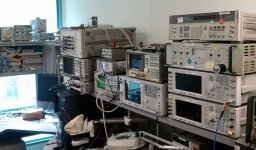
The picture shows the stuff on my desk at work. We also have a lab.
Attachments
One of the nice things about digital TV is that it either works or it doesn't (OK, not quite true but nearly true). That means that you don't have to worry too much about antenna sidelobes picking up ghost images etc. like you do with analogue. Digital has different problems, such as local impulse interference. Strangely, all EE students are taught that freedom from noise is a digital plus so it is more reliable - real life is more complicated than that!
Taking an analogue antenna which works and improving it can improve the picture. Doing the same for digital has no effect. This has two consequences:
1. simple cheap DIY antennas may make a comeback
2. simple expensive commercial antennas may be foisted on an unsuspecting public by companies who can do a bit of metalwork but would not recognise a real Yagi if it dropped on their foot. Already in the UK I suspect that many 'digital Yagi' antennas are actually corner reflectors with largely/purely cosmetic 'directors'. The corner reflector provides reasonable wideband gain, the 'directors' bump up the price.
Genuine antenna designers may have a new set of problems to solve: wideband, low local pickup (which implies good wideband baluns).
In Dallas, we have the challenge to pick up all UHF, plus "Channel 8" (on VHF Channel 9).
I'm not sure if channel 8 is still VHF? But it was at the time I designed this antenna.
Anyways, you gonna need some 7 foot bamboo sticks. A 75 to 300 balun. Two 7foot
lengths of ground wire #10 gage with all but one last foot of insulation stripped away.
And some iron or steel bailing wire (test that a magnet can stick to it)... Lastly, you
need some thin nylon tie wraps. And a low noise amplifier you can power remotely.
I do not mean one purposed for cable TV. I mean one purposed for UHF TV antenna!
If it claims more than +10db gain or won't say a "noise figure", its probably junk.
What we gonna make is a half Rhombic, or longwire Vee antenna. Sans ground plane.
No challenge here except how to terminate the open ends in free space???
What the heck did I just say????????????????????????????
OK, switch'n to Jethro mode: You gonna make really long rabbit ears. Vee shape will be
an absurdly narrow 30 degrees! And you will lay it flat in your attic, with the open end
of the V pointing toward the local stations. The Balun and amp will be at the narrow
end of the V pointing away from the stations. I remind you to keep the last (open end
toward stations) 1 foot of those ears insulated.
Now the secret sauce! Take some bailing wire (messenger wire would also do, thats the
extra steel wire that supports the weight of a coaxial cable from a pole to your house).
Wrap it spirally like a spring onto the insulation, not electrically touching itself nor the
#10 wire anywhere. Slop counts, so don't be neat about it, except be not touching!!!
Bailing snubbers will kill any signal coming in from the back before they can reflect
off the open ends. It will also prevent the antenna from resonating at harmonics of
length, and favoring some frequencies at the expense of others. OK, it will res a
little bit with VHF 9, but that was a purposeful imperfection wanted for my area...
So this picks up on the principal that the speed of radio in free space is slightly
different than in bare wire (an you best not have left all the insulation on it).
You just open at a small angle where the two speeds are compatible. Snubbed
not to resonate or favor any station or need fancy tuning. I do not know the
proper V angle or best length if you leave all the insulation on, and its never
worked out well for me if I skipped that step.
The impedance of this puppy is all over the place, and the balun isn't expected
to fix that well enough to match a 75 coax. Thats what the amp is for. Gotta
place the front end amplifier as close to that balun as you possibly can. Else
impedance mismatch to coax will set up resonances in the length of coax, and
you are back to favoring some stations at expense of others... The amp will
smooth out the impedance bumps and drive the long cable without resonance.
Be careful any splitters don't block remote power from reaching to your amp.
Be careful not lay your antenna on power wires, or horizontal metal nearby.
Sorry, if your attic if foil lined, you are screwed! Takes hours to scrape
a window in attic foil even with a sander... A or V shape bamboo frame is OK.
6 foot is probably fine if you don't care VHF... Thin vertical metal obstructions
are OK, only worry metals in same plane as the antenna, especially line of sight.
I lost 4NEC files proving directional gains. Think I simmed the snubbers as a
series string of low value resistors??? Its nothing complicated...
Anyone can bend a coathanger to pick up one station. Getting all of them and
not ever having to fool with it again is more interesting.
KD5ZXG
Last edited:
And this design is already tried and tested in the field, hundred or more times.
I was a sat installer, and made $50+ tips for terrestrial HD before sat HD was available...
Obvioulsy I had to have serious low cost of materials to earn bonus money at that.
Finding the best dollar store balun is a challenge. Some ferrites simply garbage..
Tanner once had a stash of cheap LNA's, I bought a boatload of them.
Deals exist, just finding them...
Company later gave us a professionally made HD antenna to use, but it was awful.
Multipath is a big problem for DTV, fat dipole based antennas don't have enough
directional gain to reject those unwanted reflections. The V solves this nicely.
Last edited:
I'm not sure if channel 8 is still VHF?
I looked on the site that sells antennas and found that WFAA (ABC) broadcasts on channel 8 from Dallas. KFWD is on channel 9 from Fort Worth, and there are two low power analog stations using channel 6. I didn't verify this with the FCC site.
We have a low power analog station on 6. I get fuzzy reception on the coat hanger antenna, but I don't speak it's language so I don't care. We now have VHF ststions on 7, 10, 12 and 13 from two different directions.
If it claims more than +10db gain or won't say a "noise figure", its probably junk.
I haven't found a commercial TV preamp worth using. Either the NF sucks, or the thing intermods so bad it becomes a blender. Some just don't cover all the channel frequencies.
IMD is a big deal here with a cell site on every corner and two way radio transmitters legally operating ON TV channel 14. and just below channel 7. One of the SMR towers using channel 14 is about 2 miles from my house. The 800 MHz transmitter site for the local city government is about 1000 feet from my house. When all 3 transmitters are on the air I loose channel 27. This is due to intermod in the RAT SHACK amp.
Finding the best dollar store balun is a challenge.
Again most are bad. If you decide to make your own amp, just put a M/A-COM transformer on the board. ETC 1-1-13 is the best 1 to 1 balun and the MABA-009711-ETK2MM is the best 4 to 1.
I thought DTV used COFDM, which can cope with multipath provided the path time difference is not too great?kenpeter said:Multipath is a big problem for DTV
I thought DTV used COFDM, which can cope with multipath provided the path time difference is not too great?
You think that the US would adopt the same standards as the rest of the world? Can you spell NTSC?
DTV in much of the world does use COFDM. The US DTV standard uses 8VSB. There are actually some advantages to 8VSB. Much of the US is not in a large city and 8VSB offers nearly twice the range for a given transmitter power.
Qualcomm's now defunct Media FLO system did use COFDM, but the whole tiny screen TV thing didn't sell since it carried a subscription fee, so it went bye-bye last month and took its mega strong 700 MHz IMD generating signal with it.
And it certainly takes the fun out of dx'ing when you can't even get the local stations.
Getting local ststions shouldn't bee too hard, but the days of a paper clip and a clip lead are gone. I could get 5 watchable channels with a connection to the curtain rod inside the house with analog TV, now I get 1 channel with the same antenna, and it pixellizes when you walk around the room. DTV was the reason for Antenna 1.0 which was just an oval loop of wire about 1 foot by 2 feet, mounted about a foot above the roof.
I had the dual rhombic up about 30 feet for years for TV and ham DXing. I could regularly pick up the analog TV stations from the west coast of Florida. On rare occasions I could get DX from Texas, Louisiana, and Mexico. I will rebuild the rhombic some day, but I doubt that TV DX will be the same.
There are reception reports of mostly US analog TV visual carriers using FFT analysis via EME (moonbounce) in Australia. These opportunities are now gone.
Experimental moonbounce UHF TV DX reception
Ah yes, Never Twice the Same Colour!
I did wonder whether the US does the same thing as us, but I assumed that COFDM is so common these days that almost any digital broadcast system would use it.
The funny thing about terrestrial DTV in the UK is that before they have finished switching off analogue they are offering 'HD' DTV, which partly restores the picture quality lost by digital. DTV is fine provided nothing in the picture moves!
- Status
- This old topic is closed. If you want to reopen this topic, contact a moderator using the "Report Post" button.
- Home
- General Interest
- Everything Else
- DIY TV Antenna 2.0