I made a simple TV antenna from wire several years ago. It was simply hose clamped to a vent pipe on the roof and connected to the TV with coax cable. It served me well for years receiving 30 or so "channels". It was not physically strong enough to handle birds sitting on it, thus it became deformed and reception degraded.
I came home from work Thursday and a storm had mangled it leaving me with two channels. Time for a new antenna. Since this is a DIY forum, this isn't about a trip to Best Buy. It is DIY TV Antenna 2.0.
Criteria:
Total cost ---- under $5. Preferably $0. The old coax cable will be reused. Parts to come from my junk collection.
Mounting------ Clamp to vent stack is OK, but I also have a small mast for my ham radio antenna.
Reception---- There are several Miami stations 14 miles south southeast (azimuth 155 degrees) and several Palm Beach stations 30 miles north (azimuth 5 degrees). I would like to receive as many as possible. There are more stations further north but they are 75 to 100 miles out.
A good place to find out what signals are available and how far away they are is here. Just plug in your particular city:
Choosing the Best TV Antenna for Sunrise, Florida
It is interesting to note that they recommend a $81 antenna with a rotor AND a preamplifier.
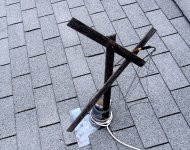
The remains of the old antenna is shown.
I came home from work Thursday and a storm had mangled it leaving me with two channels. Time for a new antenna. Since this is a DIY forum, this isn't about a trip to Best Buy. It is DIY TV Antenna 2.0.
Criteria:
Total cost ---- under $5. Preferably $0. The old coax cable will be reused. Parts to come from my junk collection.
Mounting------ Clamp to vent stack is OK, but I also have a small mast for my ham radio antenna.
Reception---- There are several Miami stations 14 miles south southeast (azimuth 155 degrees) and several Palm Beach stations 30 miles north (azimuth 5 degrees). I would like to receive as many as possible. There are more stations further north but they are 75 to 100 miles out.
A good place to find out what signals are available and how far away they are is here. Just plug in your particular city:
Choosing the Best TV Antenna for Sunrise, Florida
It is interesting to note that they recommend a $81 antenna with a rotor AND a preamplifier.
The remains of the old antenna is shown.
Attachments
Since the signals in my area are from two directions a simple dipole would work fine, and eliminate the need for a rotor. There are no stations listed in the VHF low range (54 to 88 MHz). I need to receive from channel 7 (174 MHz) to channel 49 (686 MHz). A simple wire dipole will not cover this bandwidth.
I came up with an antenna that can be built by anyone. It uses common parts available almost anywhere. The only unique item is a 300 ohm to 75 ohm matching transformer from Radio Shack. I bet the antenna will work without it.
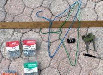
The raw materials.....
Two metal coat hangers, a strip of wood or PVC pipe for rigidity. A small barrier strip to make connection to the coat hangers (they won't solder). Some hardware, a clamp for mounting and the 300 ohm transformer.
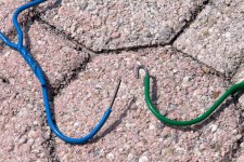
Step 1......
Strip back 1/2 inch or so of the coating on the sharp end of the coat hangers. Wire strippers work on the plastic sleeved hangers, sand paper works on the painted ones.
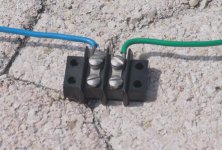
Step 2.......
Bend a small hook in the end if you are using a conventional screw type barrier strip. Teave the ends straight for a "euro strip".
Step 3 ......
Attach the hangers to the barrier strip, and bend to a 90 degree angle.
I came up with an antenna that can be built by anyone. It uses common parts available almost anywhere. The only unique item is a 300 ohm to 75 ohm matching transformer from Radio Shack. I bet the antenna will work without it.
The raw materials.....
Two metal coat hangers, a strip of wood or PVC pipe for rigidity. A small barrier strip to make connection to the coat hangers (they won't solder). Some hardware, a clamp for mounting and the 300 ohm transformer.
Step 1......
Strip back 1/2 inch or so of the coating on the sharp end of the coat hangers. Wire strippers work on the plastic sleeved hangers, sand paper works on the painted ones.
Step 2.......
Bend a small hook in the end if you are using a conventional screw type barrier strip. Teave the ends straight for a "euro strip".
Step 3 ......
Attach the hangers to the barrier strip, and bend to a 90 degree angle.
Attachments
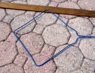
Step 4.....
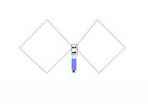
Stretch the ends of the hangers out to form a diamond.
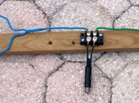
Step 5......
Attach the 300 ohm transformer to the terminal block.
Step 6......
Mount the assembly to a small piece of wood or PVC pipe.
Stretch the ends of the hangers out to form a diamond.
Step 5......
Attach the 300 ohm transformer to the terminal block.
Step 6......
Mount the assembly to a small piece of wood or PVC pipe.
Attachments
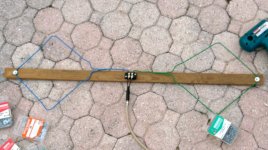
Step 7........
Attach the coax cable to the 300 ohm transformer.
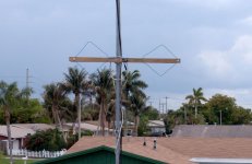
Step 8........
Mount the completed antenna in a manner such that it is stable. The ends of the wood support should be horizontal and perpendicular to the desired signal. I used a clamp from an old antenna. The installation in the photo shows mounting with the desired Miami signals coming from in front of the camera, through the tall palm trees in the center of the picture. The Palm Beach signals come from behind me and slightly off axis.
Attach the coax cable to the 300 ohm transformer.
Step 8........
Mount the completed antenna in a manner such that it is stable. The ends of the wood support should be horizontal and perpendicular to the desired signal. I used a clamp from an old antenna. The installation in the photo shows mounting with the desired Miami signals coming from in front of the camera, through the tall palm trees in the center of the picture. The Palm Beach signals come from behind me and slightly off axis.
Attachments
Does it work??????
Well I wouldn't expect this type of antenna to receive distant signals, so don't make one if the transmitters are 50+ miles away, or operating at low power.
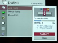
My antenna is mounted about 5 feet above the roof, at about 20 feet above the ground. I connected it to an LG 32 inch TV with about 35 feet of coax cable. I ran a scan which resulted in 53 "DTV channels" and 1 analog channel.
All of the full power DTV signals from Miami show 6 signal bars. The West Palm Beach stations show 4, 5 or 6 signal bars. A few of the low power TV stations in both markets show 3 bars but the picture quality is good (no pixelation).
I get signal from two of the Ft. Pierce channels which are 75 miles away and off axis. Both show only 1 bar and the picture is unwatchable.
Dissapointment.....
I can't get Miami channel 9, which is a low power TV station only 14 miles away (actual TX channel is 44). I could not get this one with Antenna 1.0 either, even with a preamp.
Next step.....
I built a preamp for Antenna 1.0. Unfortunately water got inside. Water + electricity + copper = the Green Growth. Time to make a new one. Total cost is $10 to $20.
Well I wouldn't expect this type of antenna to receive distant signals, so don't make one if the transmitters are 50+ miles away, or operating at low power.
My antenna is mounted about 5 feet above the roof, at about 20 feet above the ground. I connected it to an LG 32 inch TV with about 35 feet of coax cable. I ran a scan which resulted in 53 "DTV channels" and 1 analog channel.
All of the full power DTV signals from Miami show 6 signal bars. The West Palm Beach stations show 4, 5 or 6 signal bars. A few of the low power TV stations in both markets show 3 bars but the picture quality is good (no pixelation).
I get signal from two of the Ft. Pierce channels which are 75 miles away and off axis. Both show only 1 bar and the picture is unwatchable.
Dissapointment.....
I can't get Miami channel 9, which is a low power TV station only 14 miles away (actual TX channel is 44). I could not get this one with Antenna 1.0 either, even with a preamp.
Next step.....
I built a preamp for Antenna 1.0. Unfortunately water got inside. Water + electricity + copper = the Green Growth. Time to make a new one. Total cost is $10 to $20.
Attachments
Hi ya George! I'm assuming you did the math.each side of the 'diamond is quarter wavelength? If I recall the terminus of the diamond should come right to the terminal. I don't recall the lobes of this type antenna, front & back?
I "mathed up" log-periodic and a collinear array in school.....never built of course...the collinear was for car mounted cell-phone F ...with a lobing pattern that would reach several factors farther.
___________________________________________________Rick........
I "mathed up" log-periodic and a collinear array in school.....never built of course...the collinear was for car mounted cell-phone F ...with a lobing pattern that would reach several factors farther.
___________________________________________________Rick........
Attachments
Hi ya George! I'm assuming you did the math
Nope, no math, just a stupid idea to prove a point. This isn't a true diamond antenna since the diamonds are seperated and not even the same size. I couldn't find two hangers that were exactly the same.
This started as a discussion at work. I am an RF engineer designing transceiver equipment for the 100 MHz to 1 GHz range plus a few higher frequency bands. I keep getting dragged into antenna discussions, where I still state that my responsibility covers the DC power connection to the antenna jack (the radio equipment). I don't know much about antennas and don't want to get involved.
There was a design for a broadband antenna which measured bad and worked worse. I joked that a coat hanger would work better. The new guys laugh at some of my statements but the old timers know better. I told people that I could make an antenna out of coat hangers but I never got to it. Yesterday I made it. Today I documented it.
I haven't decided whether I will discuss it at work yet since I may get dragged into antenna work. I may connect it to a spectrum analyzer later today if I get time. I am guessing the response drops off a bit at the high end.
C'mon!...Antennas are fun stuff! If you got the time & inclination.it is fascinating stuff imagining E & I fields flying around!...trying to "capture" them.
I'll look up the math for this one...........& yeah, theory often doesn't match "real world" results.WAY too many variables.
____________________________________________________Rick.........
I'll look up the math for this one...........& yeah, theory often doesn't match "real world" results.WAY too many variables.
____________________________________________________Rick.........
Assuming that there is no electrical connection where the wire is wrapped at the junction, this is roughly a fat open folded dipole, but with some capacitance loading at the open end. If there is an electrical connection then it is almost a fat dipole, but being thin in the middle and fat at the ends will tend to narrow its bandwidth and lower its resonance.
Given enough signal, anything will receive, and digital will either work or not. Did you mean spectrum analyzer, or network analyzer? My guess is that this would look rather lumpy on a network analyser.
Given enough signal, anything will receive, and digital will either work or not. Did you mean spectrum analyzer, or network analyzer? My guess is that this would look rather lumpy on a network analyser.
Nope, no math, just a stupid idea to prove a point. This isn't a true diamond antenna since the diamonds are seperated and not even the same size. I couldn't find two hangers that were exactly the same.
Yeah, what point is that?
By diamond do you mean a quad? This is just a variation on a fan dipole or capacitive-loaded dipole, it gives a bit of length over the feed-to-end length due to capacitive loading and some broadbanding. You'd get more broadbanding if you brought the split point closer to the centre and made the 'wings' thinner isosceles triangles instead of diamonds. For a quad you need to connect to the open ends. The fact that you're picking up anything is down to signal strength and blind luck. You've got no idea what the impedance is at the feed point. You could 'design' it by looking at a local Yagi and pulling the dipole to size by eye. A bit shorter than the 'driven' element. You'd probably get a better match to the co-ax without a transformer, it'll be ~75ohms @ 1/2 wavelength.
w
Given enough signal, anything will receive,
That is EXACTLY the point I am trying to make! There are plenty of rather expensive "DTV" antennas on the market. Some of them are nothing more than amplified coat hangers, with minimal engineering effort expended. Many don't even have good amplifiers.
Did you mean spectrum analyzer, or network analyzer?
Not many of us have a network analyzer on their home workbench. I have on on my bench at work, but here at home I will settle for connecting the coax up to my nearly 50 year old HP spectrum analyzer to see what's out there.
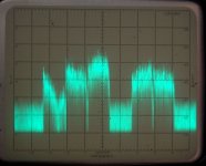
For those that are not familiar with a spectrum analyzer, I offer this simple explanation. An oscilloscope displays amplitude VS time. Both scales are usually linear. A spectrum analyzer displays amplitude VS frequency. The amplitude scale is usually logrithmic (in dB's). The FFT analyzer often used to display harmonic spectra IS a spectrum analyzer. The FFT analyzer we are used to works at audio frequencies, but they are available into the GHz range. My RF spectrum analyzer is an old tech swept LO analyzer. It goes from 0 to 1250 MHz.
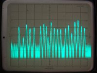
The first observation I got when I connected the coat hanger antenna to the spectrum analyzer was a surprise to see strong signals from 88 MHz all the way up to 930 MHz.
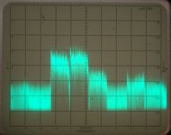
The first photo shows the FM broadcast band (88 to 108 MHz). There were many strong signals in the -50 to -60 dbm range.
The second photo shows the VHF high TV band (174 to 216 MHz). Channels 7, 10, 12 and 13 are visible. 7 and 10 are Miami channels, 12 and 13 are in West Palm Beach.
The third photo shows a portion of the UHF TV band (470 to 698 MHz). Channels 18, 19, 20, 22, and 23 are visible.
Attachments
You've got no idea what the impedance is at the feed point.
You are right. I have access to good equipment at work but I am hesitant to bring this into work and admit that I might have an interest in antennas. I have too many responsibilities as it is.
You'd probably get a better match to the co-ax without a transformer
Maybe, maybe not. I could do some real experiments, but I needed a quick antenna using stuff that I had on hand. You could analyze it to death and pick apart all the flaws, but I would rather have the TV working. It does.
You could 'design' it by looking at a local Yagi and pulling the dipole to size by eye.
A Yagi by design has a very narrow bandwidth and is quite directional. I wanted exactly the opposite. In this case I "designed" it by stretching the coat hangers to fit the piece of wood that I had.
The fact that you're picking up anything is down to signal strength and blind luck.
Granted the signals are relatively strong. However multipath can be a killer with the blind luck approach.
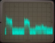
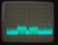
The first photo shows the upper end of the UHF TV band. Channels 46, 47, 48 and 50 are visible. Channels 44 and 51 are in the noise. They can be seen at narrower span and bandwidth settings.
The second photo shows a few SMR carriers around 865 MHz, two WCDMA channels in the 870 to 880 MHz range and a few cellular carriers above them. They are from a cell site about 2 miles away.
There are some paging carriers in the 930 to 931 MHz range not shown.
Attachments
Given that you are using it over a frequency range of 4:1 the transformer is probably helping, on average. You may get 75ohms at the first half-wave resonance, which the transformer will change to 19ohms but at the full-wave resonance you could get many hundred ohms (or more) so the transformer will bring it down.
I agree with your comments about many TV antennas: modern manufacturers seem to come up with some pretty arrangement of wires and then try to make up for the awful performance by adding a preamp (which could easily make things worse by adding intermodulation).
My guess is that in your situation the right answer is some variant of the fat dipole or discone, although 4:1 may require some form of log-periodic structure.
If you want horizontal polarisation then a biconical arrangement will do 3 octaves, maybe 4. and give you a constant impedance, probably not too bad a match to 75 ohms. You can build it with a wire frame if you don't exceed 0.2 lambda max spacing. The slant length of the cone is the free-space quarter wavelength at the lowest frequency. Wire all the ends of the 'cone' together. Move the cones in and out to get best response, spacing probably an inch or less at these frequencies, but not critical. Profile of the cone is an equilateral.
w
w
Last edited:
make up for the awful performance by adding a preamp (which could easily make things worse by adding intermodulation).
Intermod is a much bigger problem here than in many areas. City hall is line of sight, and about 1200 feet away. There are UHF and 800 MHz transmitting antennas on the roof. There is a cell site 1000 feet away, but it is 1.9 GHz. There is a mega cell site about 2 miles away that serves the eastern everglades. It has every cellular carrier on it plus several SMR antennas and it is cranked up. When the right combination of them transmits I lose TV reception on some channels, without an amp! Whacks my cellular reception too. Part of my job is investigating public safety to cellular and cellular to public safety interference.
Many high priced antennas have a rather useless amp. In fact the spectrum analyzer revealed that my Radio Shack "80 channel" distribution amp is actually costing me 3 channels. Time to make a new amp.
Connecting the antenna to the TV nets 54 channels. Adding the amp nets 51 chanels. Why? It chops off everything above 620 MHz. The antenna picks up virtually nothing below 50 MHz, but I see all sorts of "stuff" below the FM broadcast band when the amp is inserted. These are intermod and mixing products. The frequency response problem is costing me channel 9. What?
If you want horizontal polarisation
All TV signals in the USA are and always have been horizontally polarized. Many FM broadcasters have started using circular polarization as a compromize between home antennas which are horizontal, and car antennas which are typically vertical.
TV signals in the USA were assigned "channel numbers" spread across 3 "bands" a long time ago. Channel 1 was taken away to become the 6 meter ham band. Channels 2 through 6 (54 to 88 MHz) are in the VHF low band. Channels 7 through 13 (174 to 216 MHz) are in the VHF high band. Channels 14 through 51 (470 to 698 MHz)are UHF. Channels 52 through 69 were taken away with the DTV transition for the 700 MHz commercial, public safety, and high speed data (LTE) bands. Channels 70 through 83 dissapeared 20 years ago to become the 800 MHz cellular, public safety and SMR bands.
Along with the DTV transition broadcasters got new frequencies, but kept their old channel numbers. So now the number displayed on your TV bears no resemblance to the actual frequency. The "mapping" of channels to frequencies varies with geographical location. So here channel 9 is broadcast on channel 44, beyond the passband of the Rat Shack amp.
the right answer is some variant of the fat dipole or discone.......a biconical arrangement will do 3 octaves, maybe 4. and give you a constant impedance
I had an old military surplus biconical antenna, but I gave it away years ago. It shouldn't be to hard to make another. I think a biconical or modified rhombic would be good choices for Antenna 3.0, but for now I have a working zero cost antenna which can be used as a reference. Let's see the unit of measure for all new antennas is dbch (db referenced to a coat hanger)!
I am going to concentrate on the amplifier next. I had built one about a year ago using a MMIC from Hittite Microwave. It has a noise figure of 1.1 db, an IIP3 of +20 dbm and a gain of 15 db. It is specified for 550 to 1200 MHz, but has some gain down to 160 MHz. It worked well, but drowned inside my leaky housing. I don't have any more and they are not generally available. They were left over from a work project.
There are hundreds of MMIC's out there. I will choose a new one based on IIP3, NF, and gain in that order. Based on what I see on my analyzer I will need a wider frequency range too.
With lots of strong signals maybe you need a tube preamp! Your problem is that with such a wide bandwidth you need to worry about IP2 as well as IP3. 6DJ8 running parallel grounded-grid?
I'm sure Wavebourn will have some wonderful Russian military valve he can tell us about!
I'm sure Wavebourn will have some wonderful Russian military valve he can tell us about!
My suggestion was slightly tongue-in-cheek! Yes, I guess suitable FETs would be best - but do you really need an amp? Since your two directions are back-to-back why not make an antenna with deliberately very poor front-to-back ratio but low sidelobe response? Some sort of vertical stacking to get gain. Two wideband dipoles suitable phased would do the trick.

- Status
- This old topic is closed. If you want to reopen this topic, contact a moderator using the "Report Post" button.
- Home
- General Interest
- Everything Else
- DIY TV Antenna 2.0