Hello Folks,
I would like to see more options when building a remote PSU for power amp.
The amp that I am building does not have room for all PSU components. So I would like to know more pros and cons for different configuarations;
My amp have room for the voltage regulators and may be the bridge recitifier but not the filter caps banks and the transformer.
Option
A/ -- Build entire separate PSU connect to amp via 3 foot long DC power cord 2sets, one for poistive and one for negative.
B/ -- Build PSU with only transformer, bridge rectifier, filtering caps then connect to amp where the voltage regulators can be located within the amp chassis closer to the power transistors.
Thanks
Chris

I would say skip the idea and build the PSU together with amp. It ads nothing to have long wires, infact I think this is a disadvantage. I can see a advantage for pre amps and MC preamp in particular.
For power amps it's common knowledge for striving to compactness, short wires and low resistance and inductance. It's also better from a RFI perspective, smaller antenna.
For power amps it's common knowledge for striving to compactness, short wires and low resistance and inductance. It's also better from a RFI perspective, smaller antenna.
I think split PSU has merits: box 1 with xform, bridges, moderate capacitance; box 2 with main caps and active circuitry. This provides much greater isolation from mains noise and transformer EMI than is generally possible in all but the best layouts. It is a lot of effort to implement though.
chris ma said:A/ -- Build entire separate PSU connect to amp via 3 foot long DC power cord 2sets, one for poistive and one for negative.
B/ -- Build PSU with only transformer, bridge rectifier, filtering caps then connect to amp where the voltage regulators can be located within the amp chassis closer to the power transistors.
Hi,
What's maximum DC current thru cord (amp power)?
"voltage regulators" are for power amp or for low level circuitry?
Do you think about separate power supply for each amp?
3 foot?...... Long distance.
Regards
Hi,
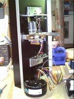
I am using two of those group buy heatsinks which is 11"X11"X2.75" each.
For each channel there are two heatsinks stacking on top so the amp is standing 22" high already. It is kind of like a large plate amp ready for future(may be) speaker project. The PSU will be regulated between 20 to 28 V and bias will be between 3.5A to 4A. Transfomer is 22-0-22 400VA
It is going to be mono block with it's own PSU.
The plate amps although it seems big but it is rather thin so there is no room for the PSU, just the amp is measured at 11"(w) X 22"(H) X 8"(D) the depth part includes the fins of those heatsink.
Chris
Banned
Joined 2002
I would do this. You say you use 2 of those heat sinks per amp and it makes them 22" tall. Why not use heat sinks on both sides for lower height?
3 feet of power cord from supplies to the amp will definitely introduce the sonic signature of the cable to the sound. Also, buildinf separate PS is like building two amps instead of one. IMO, the drawbacks involved with separate PS are bigger than possible gains.
3 feet of power cord from supplies to the amp will definitely introduce the sonic signature of the cable to the sound. Also, buildinf separate PS is like building two amps instead of one. IMO, the drawbacks involved with separate PS are bigger than possible gains.
Hmchris ma said:The plate amps although it seems big but it is rather thin so there is no room for the PSU, justhe amp is measured at 11"(w) X 22"(H) X 8"(D) the depth part includes the fins of those heatsink.
 why must this amp have so weird form factor? It's a little bit "design rather than function"
  I can understand though if you have a thing for this design.
chris ma said:The PSU will be regulated between 20 to 28 V and bias will be between 3.5A to 4A. Transfomer is 22-0-22 400VA
Hi,
You can't get stabilised 28V/4A with secondary voltage of 22V. Maximum voltage is ca 22-23V, IMHO. Have you considered power consumption (and heating) on active devices in PS? In your case, I think that 'A' would be a slightly better solution (transformer, bridge, caps, voltage regulators in one chassis). Inside the amp chassis, place additional elco caps and paralleled small block caps. Mono block is a better choice here (avoids ground loop problems and provides better isolation between amps).
Are the amps class A?
Regards
peranders said:why must this amp have so weird form factor?
Maybe....active speaker...amp on rear speaker side..

moamps said:
Maybe....active speaker...amp on rear speaker side..
Yes, that is what I have in mind, they are classA mono blocks, I already have two high power JLH and going to use these coming two for bi amp, later on when money is plenty haha oneday I hope then active speaker...that's why the design choice. With the way the heatsinks mount as is even if I were to build the PSU inside that will push the amp 6 to 7 inches higher and the internal wiring would still be over 18 inches or so...
Recently I tried one test with just a kiddies toy compress sniff around the power amps components, yes there are strong magnetic fields around the filtering caps and certain position of the tor. transformer, I guess because of the high current on the supply rails..not around the bridge rectifier though..
Chris
Also, I would like to toy with the air coil idea, there is a guy deals with magnet wires I have yet to track down to get the pricing details, I heard that he sells awg 14, 12 types by the pound, may be $5cdn per pound, so for each +ve and -ve rail with 2 mono blocks I can get 5 pound per rail just to see if the LC after the bridge before the voltage regular will help if anything.
And air coils have strong magnetric fields too I hear..That make think more to build it separate with option b/.
Just want to know more potential problem area to avoid/ proceed with caution I guess.
Chris
And air coils have strong magnetric fields too I hear..That make think more to build it separate with option b/.
Just want to know more potential problem area to avoid/ proceed with caution I guess.
Chris
no more?
Thanks for the comments so far folks.
But are there anymore pros/cons for long DC supply leads, any suggestions to minimise the negative impact, any remedies at all, may be I can use several 0.1uf caps along the +ve rail and ground, -ve rail and ground all the way from the power supply case into the amp case? What is a good antenna killer?
Thanks
Chris
What is the dissipation of the amp?
The reason I ask, is that you may need pretty thick cables for the interconnect. For instance, to avoid noticable dimming of a 12V 50W Halogen lamp you need to use 2.5mm2 cable for any run longer than a couple of metres. And if you go up to 5m, the cable becomes noticably warm to the touch as well.
The reason I ask, is that you may need pretty thick cables for the interconnect. For instance, to avoid noticable dimming of a 12V 50W Halogen lamp you need to use 2.5mm2 cable for any run longer than a couple of metres. And if you go up to 5m, the cable becomes noticably warm to the touch as well.
my suggestion is to bypass the supply on entry into the amplifier with 0.1 uf ceramic caps and maybe place some buffer electrolytics close to the amplifier and once once again bypassed.
A good cheap interconnection are the hubbel or siemans twist lock connectors which can except up to 10ga wire and they are idiot proof so you cant plug them in wrong and you can get them in as high as a 25 amp rating.....I use them extensively in all my industrial applications
DIRT®
A good cheap interconnection are the hubbel or siemans twist lock connectors which can except up to 10ga wire and they are idiot proof so you cant plug them in wrong and you can get them in as high as a 25 amp rating.....I use them extensively in all my industrial applications
DIRT®
- Status
- This old topic is closed. If you want to reopen this topic, contact a moderator using the "Report Post" button.
- Home
- General Interest
- Everything Else
- Pros/Cons Remote Power Supply