I am looking to build a unbalanced to balanced op-amp based converter that will work well in a noisy electrical environment(automotive).
The source device has a Sanyo LC75412 Volume controller IC that has 4.5V dc offset on the output that is blocked by a 10uf cap. I don't know how to figure the output impedance. I would imagine i need to add a resistor to ground after the cap and this would set the output impedance??
The source will feed the Unbal to Bal converter that will then run 10-15 feet over shielded twisted pair cable to an amplifier with Balanced inputs with a listed input impedance of 10k ohms
The amplifier also supplies +/-15vdc so I have bi-polar supplies to work with for the op-amps(more on this below). with that info i started looking at schematics online.
Rod Elliot has several published designs i have looked at. all are variations on the theme. Looking at his project list:
Project 14 Bridging Adapter For Power Amps
Project 51 Balanced Line Driver & Receiver
Project 87 Balanced Transmitter and Receiver II
are a few that all seem to perform the same sort of task. Which is best? and understanding that an auto electrical environment has a lot of noise on the ground and that the unbalanced audio output has to be referenced to this noisy ground. I am wondering if there is a design that is best suited? maybe one that offers some form of unbalanced side - noise rejection? what about something that would reference both the cars +12V and ground and reject and common mode noise? as an alternate. there is no reason why this would have to run from the +/-15vdc supplies if running the converter from the single +12V supply would help this noise rejection.
* I am posting this here as i think the subject of a noisy electrical environment is more to the fact than WHAT the application will be used for. I am looking for help from fellow DIY-ers that have understanding of op-amps and there applications rather then something that is car audio specific.
(sidebar)
Interestingly enough. the amplifier( a soundstream Ref 644s) uses a 6 pin mini din plug that has 2 channels of balanced audio plus +/-15vdc supply!! so i have a bi-polar supply to work with! At one time several of the higher end auto amp companies tried to push balanced audio for autosound. why this never caught on in the aftermarket i will never know as this seems like a VERY logical place for balanced audio connections. OEM manufacturers use balanced audio all the time for factory systems...anyway. the Input plugs for these amps use a 6 pin mini din cable and at one time they offered a box to do exactly what i am trying to do. but these boxes are few and far between and stupid expensive if and when you can find them. Building one is a better option. So I am lucky that i have a filtered +/-15vdc bipolar supply to work with already.
Last edited:
Why re-invent the wheel? Unless your line impedances are precisely matched (e.g. 0.01% resistance difference), the noise immunity will not be all that great.
There are ICs which package all the components together for you, and come in DIP packages so normal humans can use them in their projects. See:
http://focus.ti.com/lit/ds/symlink/drv134.pdf
http://focus.ti.com/lit/ds/symlink/ina134.pdf
These are around $5-$10 each, but are very high performance and would cut to the chase, assuming this approach solves your problem.
-Charlie
Wikipedia on Instrumentation Amplifiers
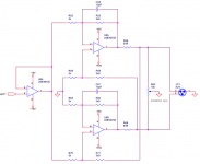
The first two op-amps form a differential in to differential out circuit. By grounding one input, you'd get a differential voltage out that is proportional to the input voltage.
Another option is to use the circuit I used in my preamp (below).
To adjust the symmetry, drive the input of the circuit with a function generator, connect the (+) output (pin 2 of the XLR) to channel 1 of an oscilloscope, and connect the (-) output (pin 3 of the XLR) to channel 2 of the scope. On the o'scope select INVERT on channel 2 and perform CH1+CH2 (most scopes - even ancient ones - are able to do this). Adjust the SYMMETRY ADJ for minimum waveform amplitude on the o'scope.
Attachments
Last edited:
The balanced output side is not the issue. it is the grounding of the unbalanced side that I am more interested in. and maybe it is not as much of an issue as i think it is?
Use a differential (balanced) input on the destination device. Someone mentioned just grounding the '-' input and that's true but WHERE you ground it will make all the difference. Your audio source makes a signal relative to ITS ground but its ground may be quite different from elsewhere. That difference in grounds IS the noise you're trying to eliminate. You ground the '-' input to the source signal ground point which may not necessarily be the source power supply ground point. I've used this in a car years back that ended up with no trace of alternator, ignition or CD servo noise (Sony D-25 back then).
G²
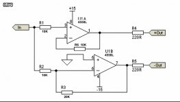
Ok so if i have done this correctly. this modified version of project 51 should give me a gain of 4x
1 volt in should give me 4 volts out. 2volts on the pos side and 2 volts on the neg side. correct??
Does anyone see a reason why these resistor values wouldn't work...or shouldn't be used??
Zc
1 volt in should give me 4 volts out. 2volts on the pos side and 2 volts on the neg side. correct??
Does anyone see a reason why these resistor values wouldn't work...or shouldn't be used??
Zc
Attachments
Ok so if i have done this correctly. this modified version of project 51 should give me a gain of 4x
1 volt in should give me 4 volts out. 2volts on the pos side and 2 volts on the neg side. correct??
Does anyone see a reason why these resistor values wouldn't work...or shouldn't be used??
Zc
You have unity gain on the '+' phase but gain of 2 on the '-' phase.
If the real issue is noise, the previously described diff input with unbalanced drive will achieve the goal with fewer components and less chance overload. Unless you've boosted the power supply voltages, you have less than 12 Vp-p and with 6dB gain your headroom is rapidly disappearing.
G²
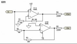
Oh i see what i did wrong. R1 should have connected to the neg side of the opamp and ground and the input directly to the + side. so that then should be a gain if 2 on the positive side as well.
I have a max input of 1.6vrms so i am hoping to get 6.4vrms out at max. with the avg listening level will be with an input around 40-100mv. I need some gain to get the SN up a little bit to keep the audio clean as it travels to the back of the car where the amp is. with balanced lines and a little bit of gain i should be ok. I can't imagine i would ever be at full volume.
with +/-15 rails. I think 3.2vrms from each side should be easily doable? even with a factor of 2 for headroom.
I can adjust the input sensitivity of the amplifier from 200mv at full power to 5v at full power
Attachments
Thanks for the feedback. I thought about adding a 20 turn trimmer someplace to null the 2 sections but I will build it first and see how off it is. I built up a similar test circuit on the breadboard the other day using scrap bench parts and one side was 2.0v out and the other was 2.12v so even with junk parts it was pretty close. using some 1% resistors should be good enough i think.
I wouldn't hesitate to use 100R resistors. The resistors also provide some basic protection and RF damping to the opamps. Using 10R may be more risky inside such a harsh enviroment like car audio. There is no reason using such a low value. Yet that it is...a small risk...nothing more, nothing less. Why not stick to the 220R?
regards
regards
Last edited:
- Status
- This old topic is closed. If you want to reopen this topic, contact a moderator using the "Report Post" button.
- Home
- General Interest
- Everything Else
- Opamp unbal to bal converter for noisey elec eviron