Not exactly imaginary but of the mind...neural response that rewards the buyer by identifying gradual accretion of sonic "improvements" over time once money is spent or tweaks are applied. If the alternate explanations are passive components changing their electrical properties over tens or hundreds of hours or altered perception, the latter seems far more likely to me.
As with most other things in the sector in which you make your money, claims are many, data is nonexistent.
Data
 :
:Cryogenic Treatment for Audio and Electronics
From the database of Cryogenic Society of America Inc:
Freezing Issue, The
O.K. On - line data seems nonexistent.
ASTM has not any either.
Very sad.
George
Yes, and of course there's all the manipulation required in making the wire into a cable and even if you cryo the cable, there's all the coiling and other handling involved after the fact.
The wire is cryoed while on the roll. The problems begin when you unroll it.

It seems we are wandering from topic and before that there was much flame throwing and conjecture which was not the purpose of this thread. We are closing it for the time being and will be reporting results when the QP's arrive here. Until that time feel free to browse the remainder of the threads here. You'd be amazed how much you are missing while posting here. Go on give it a try, we think you'll like it.
Mike Bettinger has forwarded some information. I am posting it for him. The QP's have not arrived here yet.
Bybee analysis thread response. 02/12/2011
I have followed this thread for some time out of curiosity as to what might be unearthed. I have a number of the older style Bybee devices and had experimented with them a number of years back. Back then I heard a difference when inserted into my system and I experimented with them by listening to their effects when placed in line to the speakers, in the speaker returns, the power supply rails to the output stage. My electrical examination at the time was for my curiosity and not rigorously controlled but gave me an impression as to what was going on with them.
A year or two ago I was discussing my memory of the testing results with another DIY member and sent him the devices, one as new and one where the internal resistor had been carefully removed so that the Bybee element’s response could be tested. Unfortunately my memory dictated my description of the original test setup and the devices showed nothing close to my original results. I wrote it off to being asleep at the wheel and let it go, although I could not reconcile with my sonic memory of the effect I heard, with the null results.
Following this thread inspired me to take one more look and see what came up. As before this is more for my curiosity about the world around me. Knowing my approach, instrumentation and interpretation would be 180 degrees from the highly detailed approach demonstrated on this site; coupled with the fact that I can’t invest the time needed to properly examine these devices in detail, I present my findings in a rudimentary form that should provide at least a jumping off point if someone would like to dig a bit further. The results from this round are solid and repeatable and I now understand the original ghost in my machine. Many ideas were formulated but only the ones that panned out are discussed now.
I’ll keep this as short and to the point as I can. I’ll draw no conclusions here as that is for the reader’s interpretation.
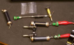
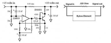
My approach to the testing and setup are similar to end use conditions. I took the output of my bench amplifier and ran the positive lead through the Bybee element, which is the high power version with the .025 ohm Pacific resistor removed and ran it into my bench speaker. Note that one of the endcaps needed to be removed to do this but the heat was concentrated on the cap itself with no direct heat applied to the element, which I might note looks to be fired onto the ceramic tube. Leads were soldered onto the copper endcaps. The test devices ended up being the element, the Pacific resistor and the stock Bybee device.
Bybee analysis thread response. 02/12/2011
I have followed this thread for some time out of curiosity as to what might be unearthed. I have a number of the older style Bybee devices and had experimented with them a number of years back. Back then I heard a difference when inserted into my system and I experimented with them by listening to their effects when placed in line to the speakers, in the speaker returns, the power supply rails to the output stage. My electrical examination at the time was for my curiosity and not rigorously controlled but gave me an impression as to what was going on with them.
A year or two ago I was discussing my memory of the testing results with another DIY member and sent him the devices, one as new and one where the internal resistor had been carefully removed so that the Bybee element’s response could be tested. Unfortunately my memory dictated my description of the original test setup and the devices showed nothing close to my original results. I wrote it off to being asleep at the wheel and let it go, although I could not reconcile with my sonic memory of the effect I heard, with the null results.
Following this thread inspired me to take one more look and see what came up. As before this is more for my curiosity about the world around me. Knowing my approach, instrumentation and interpretation would be 180 degrees from the highly detailed approach demonstrated on this site; coupled with the fact that I can’t invest the time needed to properly examine these devices in detail, I present my findings in a rudimentary form that should provide at least a jumping off point if someone would like to dig a bit further. The results from this round are solid and repeatable and I now understand the original ghost in my machine. Many ideas were formulated but only the ones that panned out are discussed now.
I’ll keep this as short and to the point as I can. I’ll draw no conclusions here as that is for the reader’s interpretation.
My approach to the testing and setup are similar to end use conditions. I took the output of my bench amplifier and ran the positive lead through the Bybee element, which is the high power version with the .025 ohm Pacific resistor removed and ran it into my bench speaker. Note that one of the endcaps needed to be removed to do this but the heat was concentrated on the cap itself with no direct heat applied to the element, which I might note looks to be fired onto the ceramic tube. Leads were soldered onto the copper endcaps. The test devices ended up being the element, the Pacific resistor and the stock Bybee device.
Attachments
Mike Bettinger cont...
I’ll attach a couple of scope images that show the results that I find interesting.
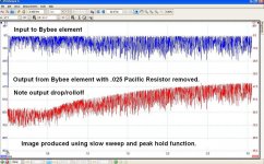
First is the frequency response of the element. The scope was set with 1v being 0 DBV. The load is my bench speaker (6.5” two way, 8ohm). The image was taken with the FFT set for 4096 bins, a 3khz bandwidth and a very slow sweep ran a number of times just for filler.
The first image shows the top trace on the input of the element, the lower is the speaker side. The crude response graph indicates a highpass response. Also of note is the insertion loss of the device.
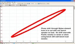
The second image shows the X/Y plot of the phase. I would sweep upward from 0hz and there was a shift below 100hz and this main one centering around 1.8-2khz.
I’ll attach a couple of scope images that show the results that I find interesting.
First is the frequency response of the element. The scope was set with 1v being 0 DBV. The load is my bench speaker (6.5” two way, 8ohm). The image was taken with the FFT set for 4096 bins, a 3khz bandwidth and a very slow sweep ran a number of times just for filler.
The first image shows the top trace on the input of the element, the lower is the speaker side. The crude response graph indicates a highpass response. Also of note is the insertion loss of the device.
The second image shows the X/Y plot of the phase. I would sweep upward from 0hz and there was a shift below 100hz and this main one centering around 1.8-2khz.
Attachments
Mike Bettinger cont...
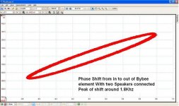
The third trace highlights the other interesting quirk. And the one that shows why earlier testing did not repeat my earlier results. The third image shows an even greater shift with both of my bench speakers in parallel. To add to this, the phase shift does not occur when the Pacific resistor is substituted for the element or when the speakers are replaced with a Dale 8ohm load resistor.
One of the effects I was predisposed to find this time around was a level sensitivity or some noticeable effect with a white noise source. Raising or lowering the test signal showed no effects and the white noise was a pointless test due to the resolution of my test setup.
One last bit of info to consider, as I have. I’ve included a schematic of what was described as an active noise reduction power supply circuit I saved some time ago. It was billed as a feed forward approach to active noise reduction if I remember correctly. (Note phase inversion). I added a block diagram of the Bybee device to ponder.
I think that covers it. Regards,
Mike Bettinger
Attachments
Of course, it would WORK with an ordinary resistor, just not as effectively. That is why Jack pays big money for the resistor used, and you can't buy it, at any price.
Of course, you have to believe in differences in 'Fermi Velocity' for this to make any sense.
Of course, you have to believe in differences in 'Fermi Velocity' for this to make any sense.
Last edited:
Mike, if I understand this correctly, you pulled the shunting resistor out. What was the DCR of the remaining unit? What was the impedance curve of the load? And did you compare results using an ordinary resistor with the same DCR as the gutted Bybee deal?
Good point, so much for deep thinking, or lack of, while messing around on a Saturday afternoon... Why I hear an effect has been bugging me and kinda blinded me to the obvious. To be complete I'll check the DCR later but as Gilda Radnor used to say, never mind.
Mike
Of course, it would WORK with an ordinary resistor, just not as effectively. That is why Jack pays big money for the resistor used, and you can't buy it, at any price.
Of course, you have to believe in differences in 'Fermi Velocity' for this to make any sense.
Hi John, I was looking more to identify what the element was doing. The resistor is obviously a fine resistor. For anyone interested there is a part number on the resistor in the picture. One would think that the effect of the device, if any, would be dictated by the fired element in conjunction with the resistor. There still might be something there. I don't know
That particular resistor is proprietary, and cannot be purchased by regular folks like you or me. It is apparently designed to go with the purifier that you measured. As I said before Mike, and for the last 15 years, other resistors CAN be used, but they will not work as well. Mike, for goodness sake, do not OPEN the resistor or drill on it in any way. I am told that it has a BeO case. DANGER! Jack has warned about this to me before. BeO for less than $1.00? I think not. Please, for your sake, everyone, read up about BeO, before trying something very dangerous. I am sticking my neck out PLENTY here, not to create any problems, but to prevent them. I have ALWAYS been on the up-and-up, SY, and I resent your opinion of me doing anything else. I personally could care LESS if anyone here ever tries a Bybee device. Jack doesn't care either, he is up to his ears in work, and is 81 years old.
I think I read somewhere that the coated ceramic sleeve measures 15 ohms.Mike, thanks! If memory serves, the DCR of the stuff on the outside is pretty significant, which is consistent with your measurements.
Eric.
Typical test gear is limited to 20Hz lower limit - this seems a big clue to where testing should be conducted.>this quantum purification technology has proven that eliminating sub-audible noise—i.e., noise unmeasurable by typical test-bench instruments--at the quantum mechanical level produces previously unattainable resolution and beauty in home audio and video.<
I don't understand what you mean, Scott - please explain ?.Split screen video is very easy to arrange and very telling.
Eric.
Stuart, you did some measurements - did you try any subjective evaluation whilst you had the QP's to hand ?.
Yes, but that's OT as well. This thread is "Measurement and Analysis," not "Listening" and certainly not "Hyping and Throwing Around Buzzwords."
I have just duplicated MB test procedure and I get the same results.
Circuit was amp out > 4 ohm resistor > speaker (single cone Bose) > amplifier speaker return.
M-Audiophile USB external sound card feeding the amplifier.
Standard Cro in X-Y mode connected across the 4 ohm resistor. (ie. one probe on amplifier output terminal and other probe on load side of resistor)
When feeding the amplifier with swept sinewave I get ellipse as per MB.

When feeding the amplifier with swept sinewave I get variable 'height' ellipse that collapses to flat line at a couple of frequencies.
This test is a measure of QP impedence vs. speaker impedence and is not revealling QP behaviour.
Next test protocol.....
Eric.
Circuit was amp out > 4 ohm resistor > speaker (single cone Bose) > amplifier speaker return.
M-Audiophile USB external sound card feeding the amplifier.
Standard Cro in X-Y mode connected across the 4 ohm resistor. (ie. one probe on amplifier output terminal and other probe on load side of resistor)
When feeding the amplifier with swept sinewave I get ellipse as per MB.
When feeding the amplifier with swept sinewave I get variable 'height' ellipse that collapses to flat line at a couple of frequencies.
This test is a measure of QP impedence vs. speaker impedence and is not revealling QP behaviour.
Next test protocol.....
Eric.
Stuart, I asked in order that if you did note audible changes that you may have some thoughts on how to measure those changes.....so did you note any audible changes on your or others' systems ?.Yes, but that's OT as well. This thread is "Measurement and Analysis," not "Listening" and certainly not "Hyping and Throwing Around Buzzwords."
Eric.
This test is a measure of QP impedence vs. speaker impedence and is not revealling QP behaviour.
Actually, it reveals the behavior quite well- Mike saw exactly what one would expect from a resistor.
- Status
- Not open for further replies.
- Home
- General Interest
- Everything Else
- Bybee Quantum Purifier Measurement and Analysis