Hi, thanks John.
Eric.
Thanks, yes I know this. That is why I asked "If the trace is across the center line..zero voltage on vertical deflection plates..."If the viewed trace is vertically displaced, as by the vertical offset adjustment, then an electron velocity change would cause the electron path curvature to change. If there is no vertical deflecting field, either electric or magnetic, I would not expect a change.
Agreed, the tube acceleration voltage would cause electrons to transit the tube at a particular speed.If there is an electron velocity change within a device, it would be over once the mean free path within the copper wires on either side of the device were exceeded..any change would dissipate as heat, then the electron is again accelerated by gradient. I would not expect any velocity change to make it to the crt.
Eric.
Does that mean that if we happen to stumble across the answer we get a visit from large men wearing sharp suits and earpieces, alighting from a big black 4x4? Or is this one of those stories where the intention is to send other people off on a wild goose chase while Uncle Sam quietly pursues quite different technology?or might get me into trouble with people bigger than me
If it does what it says it does, then it must be establishing quantum correlations between electrons (e.g. like Cooper pairs in a superconductor). Classical correlations are the reason why you don't get shot noise from a piece of wire. I find it dfficult to believe (I am being polite!) that such quantum correlations, once established, do not quickly suffer from decoherence in a normal conductor.
What I suspect it actually does is attenuate RF surface waves on a cable, by dissipating them in what is in effect a lossy choke made from fancy metal oxides. The fact that some versions add resistive "stealth" material confirms this, in my opinion. So this is a spin-off from stealth technology. Stopping RF from getting into audio components can improve the sound, yet nothing will show up in a purely audio test.
So stealth is the truth, and all the quantum stuff is the cover story? Or is the US a lot closer to room temperature superconductors than they will publicly admit? Or just yet another application of negative index metamaterials?
By the way, my experience is that some engineers (including senior academics) will sincerely believe complete nonsense. This is because they are taught just enough physics and maths to confuse themselves.
By the way, my experience is that some engineers (including senior academics) will sincerely believe complete nonsense. This is because they are taught just enough physics and maths to confuse themselves.
So this is a spin-off from stealth technology.
No, it's not. It's a resistor wrapped in a story. The measurements that John generously provided confirm that if this were a choke, it is of sufficiently small value to have negligible effect at 1 MHz. The steel leads probably have more inductance than the contained resistor.
A 50 cent resistor gives identical performance (i.e., nothing significant) in the audio band and for at least an octave above (John's data shows this to be true many octaves above, but I limited my testing to 90kHz or so).
Or just yet another application of negative index metamaterials?
I hope you're joking. There's a metamaterials company next door which works nearly entirely on military contracts. When I talked to their chief technologist (with whom I have lunch frequently- this is a very interesting subject area) about this, he was in hysterics.
By the way, my experience is that some engineers (including senior academics) will sincerely believe complete nonsense. This is because they are taught just enough physics and maths to confuse themselves.
Here I know you're not joking. Sadly.
LOL! That was great, and really to the point. But kidding aside, where does superconductivity begin?.
Superconductivity begins.....at home..
or, no, wait...maybe it was charity??

Sy is correct.
If it were not so, the .013 inch diameter wires I am now working with that are half NbTi, half copper, would not be capable of 200 ampere DC operation.
A supercon wire will skin to beat the band...the conduction begins on the surface, and goes further in as the current goes up. The surface current density is at Jc, with the depth needed to conduct the full current being imposed on the wire. So as the current rises, more and more of the super is used to carry it..it will fail once the entire volume of the super has been used to support current, then it will instantly transition to the type of conductor you mere mortals are doomed to use...resistive..bwwhhhhaaaaaahahahahah.
Cheers, John
......... Stopping RF from getting into audio components can improve the sound, yet nothing will show up in a purely audio test.
This is interesting. A lot here are of the opinion that if it can be heard it can be measured in the analogue domain at the frequencies that the ear/brain can perceive (or some would have it that the ear can hear!). Does this contradict that assertion & how is this explained?
summary of the thousands of post so far.
SY and JC have both supplied REAL data that supports the contention that the device is not significantly different in its electrical characteristics to a standard resistor.
JC claims that he can hear differences, but has not provided any data to back this up.
Numerous guesses haver been made about the possible composition and electrical effects of the device. None have been backed by any data.
Numerous posts have alluded to classified and secret status of the device and its relatives. Again, no information is provided to back this up.
The supplier of the device is independently wealthy, and drives a fettled Bentley.
Would you buy securities on this basis?
Last edited:
Hi aardvarkash10,
Yup, pretty much.
The data presented to us by SY up to now is trustworthy. So trustworthy that there is no problem with anyone else examining it and providing their findings. The rest is a smokescreen.
The claim that the technology is secret is completely baseless and falls down immediately once you look at this basic claim. If this was a secret, the government would not allow anything even remotely close to a working example out in the wild. Explanations or no! The art of reverse engineering any object is pretty well advanced these days. Once you've sold the first <whatever>, the secret is out.
The one and only reason we have not seen an improved version selling everywhere for less money is that it's painfully obvious, to even the cloning community, what is really happening here. The only effect that I can see that Bybee devices have truly had is to reduce John Curl's reputation to a tattered mess. I'm really sorry John, but this entire claim looks so bad reflecting on you that I guess you have no choice but to continue to stand behind it. For someone who has the history you do in the audio industry, this mis-step is truly sad. Your reputation, your word, is all we truly have at the end of the day. It's sad to see yours diminished over what appears to be a scam. I really hope you were simply mistaken, rather than "in on it".
The only other "bad energy" that hasn't been suggested yet are cosmic rays. Or have they? We Canadians have a huge lab that could study this in Sudbury, Ontario. You should look into their work John. Still, with the required shielding, it would be a hard sell to say that something that needs this type of examination provides any benefits up here on the surface in an audio system.
I've said it before, the best test and measurement equipment does not use Bybee devices. They are far more discerning and sensitive than the most expensive audio equipment is. There's something in that.
How about at NIST with their atomic clocks? Any jitter is really bad, any noise. They don't use Bybee devices either. Not even with primary volt standards where noise is a problem.
Give it up, John. If the Navy needed these, then NIST would have been the first kid on the block with them. You can not have equipment out in the field that performs better than equipment used to calibrate and certify them. That's a fact, Jack!
The entire construct fails upon a simple examination and logic - utterly. It's all bogus.
-Chris
Purely top-secret and classified work...
It must be a zero-point device pulling pure sound through the quantum foam to eliminate standard-model planck scale uncertainty. Or, maybe it's a state-vector collapse initiator (my personal favorite explanation). Or, even better, maybe it's a derivative of the m-brane based wave-guide transporter work at the DIA.
Oh man, I just blew it big-time.
I think I hear choppers... big black ones.
Damn...
Sy,
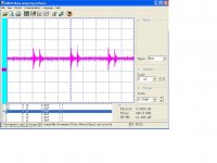
I decided to build my own "Quantum Purifier". It has about 25 nanohenries of inductance, 25 picofards of capacitance to ground the way I hooked it up. The resistance is about .003 ohms.
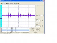
I used a #82 light bulb fed from a 9 volt battery through a 10 ohm resistor and a small ferrite core inductor to form a noise source. The DC is blocked by a .001uf film capacitor. I used my standard oscilloscope probe to look at the input to the "Purifier" and the output. Loading was only by my x1 scope probe.
The input is on the left and the output on the right. Not a big change but a measurable one! About a 10% reduction in noise!
Yes, the device and data are real! The gizmo can be described by circuit theory to a small extent. Took less than an hour to build and measure. No hard to get components. Also I believe the attenuation is scalable so larger devices should be more effective.
ES
I decided to build my own "Quantum Purifier". It has about 25 nanohenries of inductance, 25 picofards of capacitance to ground the way I hooked it up. The resistance is about .003 ohms.
I used a #82 light bulb fed from a 9 volt battery through a 10 ohm resistor and a small ferrite core inductor to form a noise source. The DC is blocked by a .001uf film capacitor. I used my standard oscilloscope probe to look at the input to the "Purifier" and the output. Loading was only by my x1 scope probe.
The input is on the left and the output on the right. Not a big change but a measurable one! About a 10% reduction in noise!
Yes, the device and data are real! The gizmo can be described by circuit theory to a small extent. Took less than an hour to build and measure. No hard to get components. Also I believe the attenuation is scalable so larger devices should be more effective.
ES
Attachments
A hunk of hookup wire wound in a coil is said to have a non-trivial effect on audio quality when only one end is connected anywhere along an audio cable or crossover. If both ends are connected to the same point, a different effect can be heard. Truth or fiction?
"There is too much anecdotal testimony to entirely dismiss the wire links in my opinion."
One can say similar things about the green marker around the outside edge of a CD as well.
"There is too much anecdotal testimony to entirely dismiss the green marker rings in my opinion." Or, just as much fun are the green LEDs in the CD bay of a CD player ... "There is too much anecdotal testimony to entirely dismiss the green LEDs in my opinion." It didn't help that the original Marantz machine, the CD-73 (I think) used green LEDs in the tray. But that was purely cosmetic and long before imagination took hold. Oops! I'll bet that was not commonly known.
We could go on and on I guess. Things get this way when personal experience of a few trump good tests and measurements by many. An understanding of the physics involved doesn't seem to count for much.
-Chris
A hunk of hookup wire wound in a coil is said to have a non-trivial effect on audio quality when only one end is connected anywhere along an audio cable or crossover. If both ends are connected to the same point, a different effect can be heard. Truth or fiction?
"There is too much anecdotal testimony to entirely dismiss the wire links in my opinion."
One can say similar things about the green marker around the outside edge of a CD as well.
"There is too much anecdotal testimony to entirely dismiss the green marker rings in my opinion." Or, just as much fun are the green LEDs in the CD bay of a CD player ... "There is too much anecdotal testimony to entirely dismiss the green LEDs in my opinion." It didn't help that the original Marantz machine, the CD-73 (I think) used green LEDs in the tray. But that was purely cosmetic and long before imagination took hold. Oops! I'll bet that was not commonly known.
We could go on and on I guess. Things get this way when personal experience of a few trump good tests and measurements by many. An understanding of the physics involved doesn't seem to count for much.
-Chris
I have no trouble dismissing green markers.
Sy,
I decided to build my own "Quantum Purifier". It has about 25 nanohenries of inductance, 25 picofards of capacitance to ground the way I hooked it up. The resistance is about .003 ohms.
I used a #82 light bulb fed from a 9 volt battery through a 10 ohm resistor and a small ferrite core inductor to form a noise source. The DC is blocked by a .001uf film capacitor. I used my standard oscilloscope probe to look at the input to the "Purifier" and the output. Loading was only by my x1 scope probe.
The input is on the left and the output on the right. Not a big change but a measurable one! About a 10% reduction in noise!
Yes, the device and data are real! The gizmo can be described by circuit theory to a small extent. Took less than an hour to build and measure. No hard to get components. Also I believe the attenuation is scalable so larger devices should be more effective.
ES
I bought one of those OWON's too, nice toy.
I bought one of those OWON's too, nice toy.
Scott, Ed, a bit OT if I may,
Did you also look at the Rigol DSO's and if so, why did you decide for the OWON?
jan didden
There is a hidden assumption in most audio testing: whatever comes out was either in the input (from my signal generator), or was generated purely internally by the device under test. There is another source of input signal: the environment. By this I mean the mains supply and surrounding EM fields. These do not necessarily enter at the input socket, although they may do this. If the environment generates a large signal this will be noticed by a tester. If, as is more common, it generates a small signal the tester might not notice or may attribute problems to the DUT or the surrounding equipment.Does this contradict that assertion & how is this explained?
Many, but not all, audio designers know nothing about RF. You can tell this from the fact that they either never mention it, or spout nonsense about it. This means that their amplifiers may have good or bad RF performance, as a matter of luck. An amplifier with good RF performance can cope with interference, a bad one not. The RF getting in will depend on the environment (e.g. nearby base stations), and the cabling. An amp with poor RF performance may be more fussy about cabling, as cables can differ greatly in their RF pickup. As a result the poorer amplifier may be regarded as having "better discrimination", because it is fussy about cables and prefers those with low RF pickup. (In my opinion, for this and other reasons, cable fussiness is a sign of poor electronic design - many people sincerely believe the opposite!).
We can't hear RF, but device distortion or overloading can convert RF into audio. In listening this might be heard as noise or vague fuzziness. Instruments might not always see it, especially if averaging is used, as the RF-induced noise is not correlated with the sig gen but neither is it random. Two people testing the same equipment in two different locations, or at the same location at different times, may get different listening results which may or may not show up in measurements. When people have gone looking for RF in audio equipment they usually find it, although levels vary greatly between different designs.
RF interference, unless severe, will not show up in audio tests. Even when visible in a measurement it might be ignored, unless the tester is aware of it as a possible issue. Perhaps audio test results should always be accompanied by a wideband RF spectrum from a standard antenna in the same room, so we know what EM soup the amplifier was sitting in.
- Status
- Not open for further replies.
- Home
- General Interest
- Everything Else
- Bybee Quantum Purifier Measurement and Analysis