Hi everybody!
I am triying to realize an input selector using relays;
I am looking for a selector that gives the possibility to switch from an input to another one pushing a button (one click >> the next input source...) or using a button for each input source...
I found this scheme but i don't understand what the first part does...
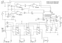
The CD4017 should be a counter (the outputs are sequences like 1000 0100 0010 0001...) driven by its clock enable input...Each output of the counter drives a bjt, and the bjt drives the input relay; Is it right?
I don't understand what the 3 nands do... Could anyone explain me what the first part of the circuit does?
Thanks,
Simone
I am triying to realize an input selector using relays;
I am looking for a selector that gives the possibility to switch from an input to another one pushing a button (one click >> the next input source...) or using a button for each input source...
I found this scheme but i don't understand what the first part does...
The CD4017 should be a counter (the outputs are sequences like 1000 0100 0010 0001...) driven by its clock enable input...Each output of the counter drives a bjt, and the bjt drives the input relay; Is it right?
I don't understand what the 3 nands do... Could anyone explain me what the first part of the circuit does?
Thanks,
Simone
Attachments
It' right.Simo88 said:Hi everybody!
I am triying to realize an input selector using relays;
I am looking for a selector that gives the possibility to switch from an input to another one pushing a button (one click >> the next input source...) or using a button for each input source...
I found this scheme but i don't understand what the first part does...
The CD4017 should be a counter (the outputs are sequences like 1000 0100 0010 0001...) driven by its clock enable input...Each output of the counter drives a bjt, and the bjt drives the input relay; Is it right?
What it seems wrong in the schematic is the clock / enable wiring because clock pin 14 is hard wired to 12 V while enable pin 13 is wired to the nand output. I think the two pins had to be swapped.
AFAIK U1A and U1B are a sort of monostable multivibrator (as SY stated for anti-bouncing purpose) whose output feeds (would feed) the counter clock while U1C feeds the counter reset pin.I don't understand what the 3 nands do... Could anyone explain me what the first part of the circuit does?
As you briefly push the S1 Pushbutton you trigger the monostable input and send a pulse to the counter while if you push the S1 Pushbutton longer than roughly 1 second (R3 C2 time constant) you reset the counter
If you are interested in using a button for each input source tomorrow I'll post a schematic.
PS As SY arrived first with the right answer you owe him olive all'ascolana and a verdicchio wine bottle
")
Simo88 said:Thank you very much!
I have never seen a multivibrator with nands...now the circuit is more clear; this is the only scheme i have found... if you have another scheme could you please post it?
The schematic is a littke bit more complex than your.
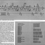
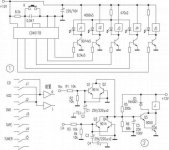
The first schematic is a block diagram
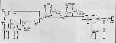
The second one is the complete analog diagram
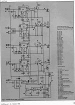
The third one is the logic diagram and the relays drivers
I didn't post the RIAA schematic
As you can see the schematics are from Audio Review feb 1983
I hope that all the schematics are readble. If not ask.
Attachments
You can debounce in hardware or software, or both -- here's an interesting guide:
http://www.ganssle.com/debouncing.pdf
http://www.ganssle.com/debouncing.pdf
Personally, wether I wanted one button to click through one at a time, or two to scroll up or down, or one for each input, I would use a picaxe programmable microcontroler.
I'm not sure how big they come, but the basic ones are in a 8 pin case, with larger ones available with more in and outputs. Just have each output going through a transistor or a small darlington pair to energise the relay, only limitation is the number of outputs on the chip vz number of desired selectable audio inputs.
The programming is really simple too. I do have a schematic that uses a rotary selector knob, and each input is switched by a relay, and the circuit also incorporates an LED per input so you can see what one is active. That can be found here:
http://users.otenet.gr/~athsam/preamplifier_modular_eng.htm
The whole page is actually for a complete modular pre-amp, but the input selector may be of some interest.
@Flyingtele
That still leaves the problem of having to debounce, although it is admittedly easier to do in software than in hardware, and is a more expensive route to go down. - Although I do have a soft spot for the picaxe chips having used them for my GCSE Design Technology project and various other gadgets I've made myself in the last year or two.
My suggestion would be to grab a schmitt Nand chip and a decade counter. The schmitt nand will let you debounce the switch and the decade counter lets you scroll through the inputs. The Decade counter outputs can then power the relays, through a BC548 transistor if necessary to provide the needed current.
The reason I say schmitt nand is that you can then use some nifty circuitry to stop the decade counter triggering from the turnon pulse when you switch the amp on. Not hugely important, but it means you can wire the input you use most to the first output on the decade counter.
@Simo88 If you are interested in my admittedly simple and untested design I can draw you out a schematic. And i suggest you test it on breadboard before you go ahead and solder it up as I wouldn't be able to test it myself as I don't have a schmitt Nand chip knocking around anywhere sorry.
@Flyingtele
I'm not sure that's the right one. I would use the 4017 IC as @gmphadte says. All you would need to do is loop the first unused output back round to the reset pin and clock it off the output from the schmitt gated push switch.
You can also do some nifty little tricks with capacitors to stop the bouncing, turnon pulses and also to give a little time delay before switching the relays so that you don't click each relay open and closed as you switch from say input 1 to 4, having to open and close relays 2 and 3 on the way through.
I realise the more things you try to get this circuit to do the more sensible it becomes to use a PIC, but that still requires a blower or at least the picaxe download circuit and all the pain of programming and debugging.
@roly3055 you beat me to a schematic but that works just as well as what I would have posted, possibly better as it does away with the schmitt chip and still debounces pretty well.
The only thing I might consider still is putting a resistor and capacitor on each of the transistor inputs so it takes them about half a second to trigger. That way it saves the relays clicking closed and open again when you scroll past them on the input selection.
I can't remember off the top of my head quite how to do it. I'll try to remember to post what i mean properly when i get home.
Hi simone,
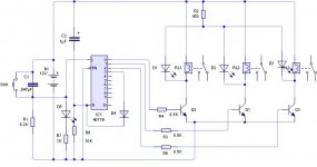
I have a nice and simple schematic using an cd4028 and an uln 2004a some diodes and resistors with led indication. Its an elektuur design I slightly changed. I use it on my mark kelly controller board to switch speeds and stop. Its works nice. I will post a schematic tomorrow.
greetings roy
I have a nice and simple schematic using an cd4028 and an uln 2004a some diodes and resistors with led indication. Its an elektuur design I slightly changed. I use it on my mark kelly controller board to switch speeds and stop. Its works nice. I will post a schematic tomorrow.
greetings roy
Simo88 said:Thanks for the schemes...
It's quite difficult to read them... where can i find a copy of audioreview? is it possible to find it on the net or to order it?
I posted the schematics in so bad resolution due to the 100k image limit of this forum.
If you send me your email I can send you the whole paper in higher resolution.
The www of Audioreview is www.audioreview.it . You can ask then if they have it.
- Status
- This old topic is closed. If you want to reopen this topic, contact a moderator using the "Report Post" button.
- Home
- General Interest
- Everything Else
- Input selector