What is the equipment. it would not be at all unlikely it is a house number.
And as to google, if that whole number is not all on one line, try parsing it as some could be a date code instead fo part of the part number.
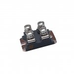
I just googled M50D06 and go a pile of data sheet hits, many of which mention M50D060S as well.
And as to google, if that whole number is not all on one line, try parsing it as some could be a date code instead fo part of the part number.
I just googled M50D06 and go a pile of data sheet hits, many of which mention M50D060S as well.
jacco vermeulen said:
Jacco,
Thank you! I have found a site that was in Russian that mentioned that part number and datasheet. I managed to find it but was unsure if it was in fact the correct item.
That's a pretty hefty IGBT!! I spent a great deal of time trying to find a cross referenced match and nothing i found has the same specs at 100 dec C.
Please take a look at these two parts and tell me if one would work better then the other and if either are a close enough match??
http://www.fairchildsemi.com/ds/FG/FGH50N6S2D.pdf
http://www.irf.com/product-info/datasheets/data/irgp50b60pd1pbf.pdf
I think the Fairchild product specs look a bit better. a bit higher rated. But i have always had good luck with IRF stuff.
This is a switching power supply for a Behringer Mixer/Amp with a high powered stereo amp section. I expect it will be abused by its users and the amp pushed to clip quite often.
As i understand it. Yamaha uses these same components in there products.
Zc
Enzo said:What is the equipment. it would not be at all unlikely it is a house number.
And as to google, if that whole number is not all on one line, try parsing it as some could be a date code instead fo part of the part number.
I just googled M50D06 and go a pile of data sheet hits, many of which mention M50D060S as well.
Thanks Enzo, I spent about hour and a half googling, bling-ing, yahoo-ing every possible way! I usually do that first and then when i have given up i post here! LOL! and usually someone here has the info right away!
Zero Cool said:specs
Dave,
the Fairchild part passes the 50A at 100C mark, no ?
IXYS manufactures similar/higher spec IGBTs, e.g. IXGK50N60B, likely cheaper.
Or Advanced Power parts, like APT40GP60B(+something)
I suppose that the package is the limiting problem.
Behringer PMP880S, 3000 and PMP5000.
Mmm, speaking of a nice rock solid package.
Attachments
jacco vermeulen said:
Dave,
the Fairchild part passes the 50A at 100C mark, no ?
IXYS manufactures similar/higher spec IGBTs, e.g. IXGK50N60B, likely cheaper.
Or Advanced Power parts, like APT40GP60B(+something)
I suppose that the package is the limiting problem.
Behringer PMP880S, 3000 and PMP5000.
Yes the Fairchild part does 60A @ 110 Deg C!!! and from the specs looks like the best match. it was designed for switching supplies. But i was looking at all the other specs wondering if it was close enough in that regards.
The IRF Part does 45A @ 110 Deg C which is close.
I have two of these Mixers both with failed power supplies. I have no doubt they get the crap beat out of them so upgrading those IGBT's a little bit wouldn't hurt. and the Fairchilds are rated at 75A @ 25deg C so maybe they will survive a bit longer. But please advise if the rest of the specs look like they match close enough????
I looked at all the IXYS stuff that Digikey has and nothing came as close as the Fairchild. and I haven't looked at the APT Stuff.
These Behringer are quite a piece of S***t, when it comes down to repairing them. I found a company that sells complete electronic modules at really convenient price(ex. a brand new power supply of the PMP5000 costs around 150€+shipping costs).
just while writing this reply, I have one on my desk with burnt IGBTS.
I give you an example of bad design: Look at the Power Integrations web page and find the application note for the TOP221(in Behringers it is used to power the control circuitry of the main PSU). You will see, that there is a component (in parallel with the primary of the transformer), a clamp diode, to absorb the peaks of energy developed by the primary winding when the power transistor in the TOP221 is not conducting. These peaks are even bigger when the small power supply approaches some overload condition(like a short circuit). Then all the energy stored in the output inductance gets multiplied by the transformer ratio back to the primary and it very easily destroy the TOP221 and associated components. On Behringers you won't find such a diode - a mistake in the design. My belief is that the entire Behringer(also known as Berlinguer...) PSU is full of this kind of design mistakes which lead to it's premature failure.
(the C15 also is critical for the correct operation of the Half Bridge topology PSU and in Behrigers is rated at 400V!?)
However all the components are on stock at Farnell.
http://pms-electronics.com/(seller of Behringer spares)
Cheers
Ivan
yeah i gave up on mine. I checked every component on the PSU replaced all that were bad, crossed my fingers and fired it up...nothing, checked and checked again...nothing.. then while it was on i started checking voltages and after a minute or two it started making noise like it was trying to run and before i could get to the power switch POOF away it went again.....Junk!
Behringer again...
I made a step forward in repairing the PMP5000. I repaired the power supply, tested it on bench(without the power amp module), it worked fine(loaded with a 500W lightbulb across the +/-80V outputs).
I performed all the testing with an isolation variac.
When I connected the power amp, then I almost got fireworks again...

One of the channels is defective and it kept the HV output of the PSU shorted.(Fortunately I powered the stuff with the variac and I was rising the voltage slowly)
Now I'm facing the problem of Behringer hiding the datasheets of the HCA9001 and similar stuff.
I will probably have to replace the entire power amp module.
I promised to myself: once I'm finished with this, to NEVER REPAIR BEHRINGERS AGAIN!!!
I made a step forward in repairing the PMP5000. I repaired the power supply, tested it on bench(without the power amp module), it worked fine(loaded with a 500W lightbulb across the +/-80V outputs).
I performed all the testing with an isolation variac.
When I connected the power amp, then I almost got fireworks again...
One of the channels is defective and it kept the HV output of the PSU shorted.(Fortunately I powered the stuff with the variac and I was rising the voltage slowly)
Now I'm facing the problem of Behringer hiding the datasheets of the HCA9001 and similar stuff.
I will probably have to replace the entire power amp module.
I promised to myself: once I'm finished with this, to NEVER REPAIR BEHRINGERS AGAIN!!!
Hey everyone. I'm working on a PMP3000. Here's the schematic of the power supply that I've put together so far: http://jonathon.onthefive.com/temp/pmp3000psu.png
Upon firing it up after replacing a broken fuse holder, I smoked one of the large ceramic resistors at the input (R12). As it was red hot, I assumed there was a short somewhere. Measuring across (+) and (-) at the output of the rectifier, sure enough there was a short (~0 Ohms). I confirmed that IGBTs T3 and T4 are both appear to be shorted from Collector to Emitter.
Is this the same mode of failure you saw in your mixer? How does the small PSU work? And also, can you give more details of the protection diodes? It seems like that would be a good idea to prevent transients from damaging the IGBTs.
My band has practically no money, so fixing this mixer for practically nothing would be fantastic")
Thanks a lot,
Jonathon Reinhart
Upon firing it up after replacing a broken fuse holder, I smoked one of the large ceramic resistors at the input (R12). As it was red hot, I assumed there was a short somewhere. Measuring across (+) and (-) at the output of the rectifier, sure enough there was a short (~0 Ohms). I confirmed that IGBTs T3 and T4 are both appear to be shorted from Collector to Emitter.
Is this the same mode of failure you saw in your mixer? How does the small PSU work? And also, can you give more details of the protection diodes? It seems like that would be a good idea to prevent transients from damaging the IGBTs.
My band has practically no money, so fixing this mixer for practically nothing would be fantastic
Thanks a lot,
Jonathon Reinhart
Behringer PMP5000 problem
The usual cause of the power supply failure is a sudden failure of one of the power amp which places a short on the supply.
The ACTUAL cause that starts the problem is insulation breakdown of the circuit trace between the three drain leads of the rear-most amp and the source lead trace of the T20 and T21 pair of MOSFET's.
The resulting breakdown burns the board and the traces and fries the three switching transistors in the power amp.
On one of my units, one of the 18 volt zeners driving the gate and also the 30 milliohm metering resistor was fried. The power supply survived on that one.
The other unit most of the main power supply components were toasted, including the switching regulator IC and the driving transistors and main supply switchers. The same damage was found in the rear-most power amp.
In both cases the circuit board charred cancer had to be ground away and conductors replaced by hard wiring.
Use the series light bulb trick when powering up after repair.
I have been thinking about adding a fuse in front of those large resistors. should there be a failure, the fuse would blow and not kill those resistors.
Can anyone confirm that the PSU will run without the amp plugged into it? it would be nice to be able to test the PSU by itself first.
Zc
Can anyone confirm that the PSU will run without the amp plugged into it? it would be nice to be able to test the PSU by itself first.
Zc
PMP5000 information
Yes, the main power supply will run without the power amps connected HOWEVER there are NO bleeder resistors and the caps store a massive charge at 80 volts, and one needs to bleed the charge before connecting the amp!!!
There is so much current initially that fusing the soft start resistors is probably futile.
I just got my second PMP5000 restored and back together today. Here is the diagnosis and the work accomplished:
The rear power amp had an insulation breakdown from the drains of the three switching transistors to the source of the 9640 transistors. (These are in parallel as complement to the single other side switcher transistor)
The circuit board was bubbled and the cancer was ground out with a dremel tool. Clear epoxy was put over the area. The drains of the 9640's were drilled out and the replacement transistor drains were left full length and sleeved.
Since the grinding removed the source tie trace between the 9640's, this was hardwired with hookup wire.
Since the grinding removed ALL the drain connections of the 3 switching transistors, these were hardwired between them. A hardwire connection was also made to the drain of the single transistor to connect it to the toroid inductor lead closest to it.
Next, the 30 milliohm metering resistor on the bottom side was replaced as it had disintegrated.
An 18 volt, 500mw Zener diode (surface mount) was replaced that was shorted. This is part of the gate drive to one of the 9640's.
The amp was powered first at low voltage from current limited supply. It did not work, but since it did not smoke, it was connected to the main supply after bleeding the caps. One can turn the panel at 90 degrees and have the cables from the panel connected to the amps and supply by putting a book or spacer between the supply and the back of the panel. It still did not work.
Surface mounted transistors T12 and T16 were found to be shorted when the 30 mohm resistor opened. These transistors detect excess current in either polarity through the 30 mohm resistor and their collectors "OR" the signal into a latch of cross coupled transistors, which shuts down the drive signal to the switchers in the amp. (there are seperate ones for each side amp)
These two surface mounted transistors were replaced and the dead side of the amp came alive!
My first amp had the power supply destruction to repair and the same failed amp circuit board fireworks. In this second one, the 30 mohm resistor fused and saved the power supply.
In the my first PMP5000, the softstart resistors got cooked because I tried to start the supply before all the baddies were out. The main switching transistors were gone, the drivers of those were gone, the diodes at the gate drive were gone, several small components were gone, and the 8 lead switching control chip for the main supply was gone.
To sum it up, the failure in the rear power amp can do damage to itself and the main power supply when it arcs out. On the first unit I repaired, the 30 mohm resistor did not open and there was NOT much evidence of the arc and short in the rear power amp, but the smoking gun was there right next to the heatsink. It can easily be missed if there was little flame there and one will immediately blow up the freshly repaired power supply if one connects it again without repairing the amp section.
I repair amps all day long. my biggest so far was a 10kw crest, I use a 60 watt 120V light bulb to discharge caps. works great. I am very aware to discharge caps. killed an entire bank of output transistors TWICE in one amp long ago...I have never forgotten to discharge caps since! LOL!
I have repaired two of them now.
The HCA4001 chip doesn't go.
The original cause is a short of traces on the circuit board near the three switching MOSFETS on the amp near the back of the unit. There are two 9640's in parallel and a 250 on the other side. The burnt "cancer" has to be cut out and traces replaced with hard wiring. The switcher transistors are toast. Sometimes the 30 milliohm resistor is fried. Often the Zeners in the gate circuit of the switchers are damaged.
The gates are CAPACITIVELY coupled and usually the damage does not extend back to the drivers.
IF THE 30 milliohm resistor is damaged then surface mounted transistors T12 and T16 are toast. These transitors are over current detectors that set a latch to kill the switching signal to the power switchers in the amp.
Note that the power supply has no bleeders to discharge the 80 volt supplies, so one must discharge those before connecting the amps back up.
I can give you info how to go about repairing if you need help.
The original cause is inadequate insulation of traces between the drains of the switchers and the sources of the 9640 switchers. The damage will often destroy parts on the main power supply which played no part in the original failure.
The board is multilayer and I believe humidity enters the cut edge of the board and breaks down the VERY thin insulation of the board. (these are multilayer boards.)
Brought the second PMP5000 up yesteday
The final part of the repair was transistors T12 and T16 which detect overload current via the 30 milliohm metering resistor and set a latch which disables the swtchdriver chips.
The output switchers are capacitively coupled and damage usually doesn't go backward from the few components around the gate of the power switchers.
The insulation problem of these units near the rear power amp is the problem. It is the original failure. The arcs occur between two layers of this multilayer board. The insulation is unbelievably thin for the voltage peaks it receives. Wipes out a lot of parts and can wipe the main pwer supply as well.
I can coach anybody through restoring these if they need help.
Fredy2,
Yup that sounds exactly like what happened to mine. I will have to double check it now. I know the 30mil resistors were dead on the back channel. I did replace that. but i will check the transistors. I know I didn't discover the fault until after i blew up the PSU so i need to dig in and repair the psu again and then dig into the amp.
Thanks for all the info. how about putting together a rebuild document with photo's etc. keep working on the schematics of the PSU and amp boards! MANY of us need them!!! I keep hoping that someone "leaks" some out to the net and we can find them!
- Status
- This old topic is closed. If you want to reopen this topic, contact a moderator using the "Report Post" button.
- Home
- General Interest
- Everything Else
- M50D060S Datasheet???