The transistors you will find are gonzo. They don't survive. The short acts as a short across the 9640's first, destroying the 250 which then fries the 9640's... then if the PS doesn't fail, the 30 mohm fries followed by T12 and T16.
It is VERY important to get the burnt board material cleared out totally as it becomes conductive and you will fry the transistors again.
I wish I had taken photos of the repair... I thought about it but I was under the gun as I need the unit for a gig in Lewiston ID in a week.
I am pretty good at describing the repair. After clearing the cooked board and removing the blown three transistors, I drill out the drain hole of the 9640's. I replace the 9640's leaving the source leads a little long for a jumper between them. I leave the drain (center) lead FULL length. I sleeve the center lead as it goes through the board for the 9640's. I put a jumper between the source leads as the source trace has to be removed as it shorts to the drain leads on the next layer of the circuit board (inside layer). Next I run a continous jumper between the drains of the 9640's and continue on over to the 250 transistor and then continue to the closest lead of the toroid inductor. The exposed edges of the internal trace and that on the top of the board (the source of the 9640's) i cover with insulating epoxy making sure to have cleared ALL the burned material... remember the burn is between layers of the multilayer crcuit board.
I found that one of the 18 volt gate Zeners was shorted... so check all of those.
Since you lost the 30 mohm resistor, surface mount transistors T12 an T16 are gonzo. They are back to back sensing across the 30 mohm resistor and the base resistors ar too low to protect them from the 80 volts when the switchers short. I used 2N5501 or something like that (PNP)transistors to replace... I will have to look at the package as that PN is from memory. You will need the paste solder for surface mount to replace these. Careful use of solder wick to remove the solder first, a GENTLE pry up of the collector lead while heating it then to remove them. They are the size of a head of a pin... After the pads are cleaned, put a drop of the solder paste on each pad. With tweezers place the new part into the solder paste and a touch of the iron to each lead and then clean the residue and it is done.
I bought a neat tool from eBay. The guy will sell them for $270 as an offer. The tool is called "Smart Tweezers". Look it up... Most places want $300 but the guy on eBay will accept an offer of $270... He is someplace in Canada... neat tool and really useful for surface mount.
Last edited:
I have schematics for the unit... they are on the internet at a European site that somebody probably violated a non-disclosure agreement someplace...
In my position I don't dare divuldge the site name. You can find it and you may need to read a foreign language and register if you want to download more stuff. I sent the site a donation of equivalent of $10 I was so happy to get the info.
The drawings for the PMP5000 are under a set as:
"PMP-1280s" which has the power supply, the HCA2400 power amp and all the DSP and mixer schematics.
I just found this and up to that time I was tracing out the parts I needed. I traced enough of the power supply on the first one to repair it which took MANY components.
The site is a goldmine so PLEASE use discretion so it continues to be available.
Hi all, hopefully someone will respond to this post. After reading this post (as well as others from different sites) it seems that this channel B blowing and taking out either the amp or sometimes the psu is a fairly common problem. I have been browsing through the used gear section on Musician's Friend | Your Online Music Instrument & Pro Audio Store | Best Prices, Great Service
Buy Behringer EUROPOWER PMP5000 Powered Mixer | Powered Mixers | Musician's Friend
It looks like they have a bunch of these mixers for $231 USD with either blown amp or blown PSU (which i would suspect it has the blown amp as well). What I am wondering is if It is worth it for me to purchase one of these broken mixers with the blown amp and fix it up or if im just asking for headaches? I have the schematic from the "foreign source" and I am very comfortable with electronic repair (test and repaired $20,000 cd players/DAC's for over 3 years).
Are there any suggestions to "Beefing" up the other amp as well so it doesn't blow... im guessing a heavy gaugue jumper wire where the trace blows... upgrade the FETS? PSU mods...
Any suggestions would be grateful, is the $230+ $30 or so in parts worth it or should i look into another make model (would like to use for live shows ~200ppl and recording purposes, nothing professional just fun. Yes I have another amp to drive more speakers as well.
Thank you for your time
Dave
The problem causing this is inadequate insulation between two adjacent layers in the multi-layer circuit board. The arcing and destruction occurs between the output switched line to the filter inductor and the +80 volt traces. One has to carve out the cancer, reinsulate and replace the blown semiconductors and assorted other parts. I have refurbed two of these and have used them in gigs... It is a lot of work to refurb, especially those with blown supplies.
I have horded all the Behringer schematics from that site in case it dissapears one day. I have tried to register several times but it seems no one is minding the store so to speak. I have been hesitant to get back into mine. lots of work and many thanks for the excellent info on what the problem is and how to fix it. that makes me at least want to try it again. I have fixed many other Behringer items and have gotten quite good at it actually. have learned many techniques for working on surface mount stuff. I just got some solder paste but have gotten pretty good at working without it. I take one pad, put just a touch of solder on it, then place the part with a tweezers and hold it in place while heating the pad/part with the soldering iron until it "sets" flat. then solder the other pins. I am looking to buy a stereoscope type microscope for working on the really small stuff and have been reading about building a reflow over....just not quite "there" yet.
I have several other problem child items in shop at the moment that have been plaguing me that i need to get the %$^& out of the way!
I have several other problem child items in shop at the moment that have been plaguing me that i need to get the %$^& out of the way!
Yes, I have likewise...
I was able to register...hard with the foreign language. I did send a donation and may send more... I have archived several brands as well.
When repairing the PMP5000, it is important to clear the burnt board completely. The one required a lot of "dental" work with Dremel tool and re-insulating with epoxy.
Feel free to contact me for details on my regular email... put pmp5000 in subject as I get a lot of spam.
pmp3000
I have pmp3000 with failed power supply. So far I found that one of the soft-start resistors (10 ohm on this board for some reason, not 22) is fused, and both IGBTs are shorted. Other components don't look bad, but I did not dig deep yet. The amplifier looks fine, and power lines to it are not shorted. So I am not sure what triggered the failure.
Is it likely that just IGBTs failed, and nothing else?
Is it possible to put in some cheap transistors temporarily to test the power supply with no load? I would hate to blow expensive devices just to find out that something else is wrong.
How to test the 2153 IC?
Thanks a lot.
When you have removed the main switching transistors and restored most else, one can fire up the supply without the main switchers and observe that the 2153 is running with a scope...
You will find MANY other components blown as well, including at least one of the 4148 diodes for gate speedup drive and at least one pair of the emitter follower drive transistors A1020 and its mate.
Often a arc over in the rear amp starts the failure. In one I am working on one of the surface mount caps across the 80 volt line exploded and MIGHT have been at fault. T9 surface mount transistor is also gonzo.
WARNING: when supply has started without the amps during testing, BLEED the caps before plugging the amps back on... welding if you don''t !!!
Only work on the power supply when using an ISOLATION transformer for safety.
When you have removed the main switching transistors and restored most else, one can fire up the supply without the main switchers and observe that the 2153 is running with a scope...
Do I need those A1020/C2655 pairs in place for this trick to work?
Did 2153 die in any of yours?
In my case I also have the big MOSFET in the rear amp shorted, but I don't see any damage to the board, which could suggest an arc between the layers as you suggested. Two smaller MOSFETs look fine, 30 mOhm resistor and everything else looks fine too. So I am not still sure of the root cause.
Thanks.
Also, It looks like all of these IGBTs that we've been considering for replacement have built-in reverse-protection diodes. Are these sufficient?
sps1000/02
Where is the web site for the schemats I Have 3 units that are burned out I will try to fix them
The usual cause of the power supply failure is a sudden failure of one of the power amp which places a short on the supply.
The ACTUAL cause that starts the problem is insulation breakdown of the circuit trace between the three drain leads of the rear-most amp and the source lead trace of the T20 and T21 pair of MOSFET's.
The resulting breakdown burns the board and the traces and fries the three switching transistors in the power amp.
On one of my units, one of the 18 volt zeners driving the gate and also the 30 milliohm metering resistor was fried. The power supply survived on that one.
The other unit most of the main power supply components were toasted, including the switching regulator IC and the driving transistors and main supply switchers. The same damage was found in the rear-most power amp.
In both cases the circuit board charred cancer had to be ground away and conductors replaced by hard wiring.
Use the series light bulb trick when powering up after repair.
Where is the web site for the schemats I Have 3 units that are burned out I will try to fix them
I repair amps all day long. my biggest so far was a 10kw crest, I use a 60 watt 120V light bulb to discharge caps. works great. I am very aware to discharge caps. killed an entire bank of output transistors TWICE in one amp long ago...I have never forgotten to discharge caps since! LOL!
schemats where can i find them
Hello everyone.
New to this forum. lots of good info, Thanks.
I too have one of these pwp5000's blown power amp as everyone else.
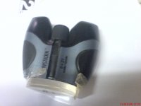
I'm not seeing the burned PCB like what was described. The 9640's and 250 is shorted and the 30mO resister caught fire and burned. (have photo' burned and cleaned up)
I'm afraid the unit may be more expensive to fix than its worth. has anyone just converted the unit to just be a mixer for use with an external amp?
Haven't had any luck with the forign website and schematic. "EMX5000" is a yamaha and the schematic doesn't match.
New to this forum. lots of good info, Thanks.
I too have one of these pwp5000's blown power amp as everyone else.
I'm not seeing the burned PCB like what was described. The 9640's and 250 is shorted and the 30mO resister caught fire and burned. (have photo' burned and cleaned up)
I'm afraid the unit may be more expensive to fix than its worth. has anyone just converted the unit to just be a mixer for use with an external amp?
Haven't had any luck with the forign website and schematic. "EMX5000" is a yamaha and the schematic doesn't match.
Techknowman,
The EMX5000 power supply is VERY similar to the Behringer (or should I say that the other way around, hmm...) The only real difference is that the Behringer uses a TOP221 switcher for the standby power supply (powering the 2153 switcher), whereas the Yamaha uses a regular linear regulator.
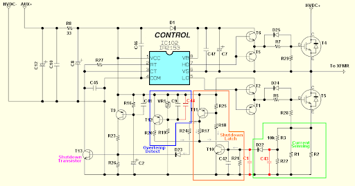
I've started changing the Yamaha to match the Behringer I've traced out. Here's what I've got so far (mostly the IGBT drive):
The EMX5000 power supply is VERY similar to the Behringer (or should I say that the other way around, hmm...) The only real difference is that the Behringer uses a TOP221 switcher for the standby power supply (powering the 2153 switcher), whereas the Yamaha uses a regular linear regulator.
I've started changing the Yamaha to match the Behringer I've traced out. Here's what I've got so far (mostly the IGBT drive):
Also, can anyone point out what Diodes they added for the TOP221 reverse protection? And what you used for the A1020 gate drive totem-pole? I've found the 2STL1360 to replace the C2655 NPN, but not anything complementary for the A1020 PNP.
nte 293 and 294 will replace a1020 and2655 where can i find a 2153 ?
M50D06S
Hi there if you Google 1MBK50D-060S you'll get the info you need. It's just an IGBT 600V 50A 200W. Hope this helps. There are two in the Yamaha BBT500H Q110 & Q111. Suggest using an equivalent though, Farnell & RS have plenty to choose from. An original will cost you about £18 each that's mega money when there are lots of compatibles.
Steve
- Status
- This old topic is closed. If you want to reopen this topic, contact a moderator using the "Report Post" button.
- Home
- General Interest
- Everything Else
- M50D060S Datasheet???