Hi all
I would like your advise on the proper way to wire the secondary of an isolation transformer, so as not to violate the electrical safety of the equipment to be connected to it ( audio gear) and to retain - as much as possible - the isolation from the noise which is superimposed on mains wiring.
I spent a few hours reading books and some more hours on the internet, but the opinions are really conflicting.
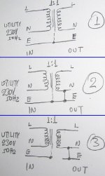
Attached is a sketching of 3 different connections.
Please commend
Best Regards
George
I would like your advise on the proper way to wire the secondary of an isolation transformer, so as not to violate the electrical safety of the equipment to be connected to it ( audio gear) and to retain - as much as possible - the isolation from the noise which is superimposed on mains wiring.
I spent a few hours reading books and some more hours on the internet, but the opinions are really conflicting.
Attached is a sketching of 3 different connections.
Please commend
Best Regards
George
Attachments
Why are 2 and 3 not equivalent ? They are both labelled E, yes? Or are you saying the output end of E is not bonded to the panel earthing conductor? It must be, no exceptions.
With very rare exceptions, 2 is the only legal method (in the USA) if you are feeding multiple equipments with this power supply. If it is only being used inside a single enclosure, then 1 can work. However, it is typically a good idea to earth the equipment at some point, even if through a resistor. A completely floating supply has its own set of problems.
What do you intend on this supply feeding, specifically?
Zigzagflux
I intend to use such an isolation transformer (IT) to feed the pre-amp, main amp, tuner and CD drive .
Richie00boy
In fact the wiring per sketch No 1 is the way that any step-up or step-down transformer is wired in any linear PSU
I have an isolation transformer (IT) in my lab, which is wired as in the No 1 sketch. I use it during repairing equipment for reducing the likelihood of becoming a spirit. So far so good.
But today morning during some mains noise monitoring, I thought of measuring the noise at the output of this IT.
Then to my surprise, I noticed that the voltages of the thus wired secondary were behaving quite strangely (strangely to me).
See attached photo.
Is it normal? Is it safe?
When the secondary is wired as per No 2 and No 3 sketches, voltages are as on the primary. No surprise.
Regards
George
Attachments
I would bet the wiring of the output of your IT is currently correct. Did you notice your measurements on the secondary don't add up to your 229Vac?
Think how the circuit works as in electron flow. The measurements from Live or Nuetral to Earth are capacitatively(?) coupled...I think that your DVOM puts such a light load on the circuit...that you can get any reading. I would bet if you loaded the circuit just a little you won't read any voltage at all. Wouldn't be baffling if you had a cheap meter & you tested both 'L' & 'N' ...and it gave you no readable voltage?
You should be able to pull down that reading with microamps & the voltage would drop.to nothing.
As has been said over & over, rectifying AC from the wall is dangerous because the live side to earth AND/OR Nuetral is hot.
Thats my take on it....I'm probably wrong in my assumptions, but....
___________________________________________Rick.............
gpapag said:I intend to use such an isolation transformer (IT) to feed the pre-amp, main amp, tuner and CD drive.
Well, not to be a party pooper, but at least in America, you are required to ground the neutral, by NEC 250-20(b)(1). The only exception that I have been able to identify would be balanced systems, which have the center tap of the transformer secondary grounded, so you have 60-0-60V. Note: this exception is still a grounded system. Since your isolation transformer does not appear to have a secondary center tap, I won't bother discussing this option.
I am not sure where the idea came from that a completely isolated system is the ultimate goal, but it's not. Ungrounded systems are prone to transient overvoltages and nondesirable capacitive coupling effects (which is why the Code limits their use).
If the transformer was exclusively used inside one single component, such as your amplifier, then you are able to leave it isolated (or resistance grounded as mentioned above). This is found in section 450, IIRC. Section 640 addresses some specific allowances for audio equipment, but there is no allowance for isolated systems feeding a power strip to multiple devices.
Others can debate the pros and cons of grounding the secondary from an audible standpoint; but sorry to say, legally it must be grounded. I am open to someone showing me a Code exception that I have missed (they are very easy to miss).
Yes, earth must be earth. /Do not defeat your safety ground!
The strange readings you get are as Richard Ellis alluded. The uA leakage currents flowing through your voltmeter are causing an AC voltage to be read. It's an artifact because the secondary if floating.
The requirement to tie neutral to earth is only at the power panel. Never do this anywhere else.
The key reason to use an isolation transformer is to protect yourself from live chassis. If you are holding a grounded (earthed) pipe for instance and touch a live chassis, the isolation transformer will prevent electric shock. You'll still get a tingle from the leakage current but it won;t stop you heart.
Remember power engineering 101 - keep one hand in pocket!")
To filter noise from the mains, you're better off with filters to target the band of interest: common mode chokes, small properly rated caps. Toroids have high bandwidth and couple a lot of cr@p. E-I iron laminated cores are pretty narrow bandwidth and help.
The interwinding screen (faraday shield) only stops common mode capacitively coupled noise, not the predominant dirty sine + RF that usually comes out the wall
The strange readings you get are as Richard Ellis alluded. The uA leakage currents flowing through your voltmeter are causing an AC voltage to be read. It's an artifact because the secondary if floating.
The requirement to tie neutral to earth is only at the power panel. Never do this anywhere else.
The key reason to use an isolation transformer is to protect yourself from live chassis. If you are holding a grounded (earthed) pipe for instance and touch a live chassis, the isolation transformer will prevent electric shock. You'll still get a tingle from the leakage current but it won;t stop you heart.
Remember power engineering 101 - keep one hand in pocket!
To filter noise from the mains, you're better off with filters to target the band of interest: common mode chokes, small properly rated caps. Toroids have high bandwidth and couple a lot of cr@p. E-I iron laminated cores are pretty narrow bandwidth and help.
The interwinding screen (faraday shield) only stops common mode capacitively coupled noise, not the predominant dirty sine + RF that usually comes out the wall
Exactly.Iain McNeill said:The key reason to use an isolation transformer is to protect yourself from live chassis. If you are holding a grounded (earthed) pipe for instance and touch a live chassis, the isolation transformer will prevent electric shock. You'll still get a tingle from the leakage current but it won;t stop you heart.
[/B]
There won't be appreciable current flowing between the isolated 'live' and the earth connection.
So, once we have moved the isolated supply off the chassis with the possibility of accidental connection to the live mains (not isolated) circuit, what's the point of the earth conductor? It seems to me that you are really dealing with a two-conductor, isolated system which is not referenced to ground (or neutral).
So once you are on the isolated side of the transformer, you need to pay attention to the fusing arrangement, since you can no longer depend on the main breaker/fuse for protection.
In spite of code 'requirements', isn't the earth really just a decoration after the isolation transformer?
BTW, there is a lot of info on this topic in marine wiring systems, where isolating the boat from the electric currents flowing around the marina can be a big deal.
Slightly (or more) baffled,
John
Iain McNeill said:The requirement to tie neutral to earth is only at the power panel. Never do this anywhere else.
Emphatically wrong!! The transformer is classified as a separately derived system, and it is required to ground one conductor. This conductor then becomes named the neutral. There are no exceptions to this; if we need to get a moderator involved in order to address the illegal suggestions that are being made, I have no problem with it.
This is good, we have a quorum of experience.
Regarding safety ground on the isolated side. I will clarify my point by saying that safety ground is a fundamental protection for persons who may come into contact with the equipment. In the event of an IT pri-sec short, safety ground will still protect the casual user.
What you do in the private of your own lab is your own concern . In this domain I agree that there are benefits to balanced power distribution
zigzagflux:
If you enforce the neutral-ground tie on the isolated side, then there must be some requirement to maintain polarity right? It sounds like you have experience in the power industry that I/we can learn from. Can you give us some more info?
Regarding safety ground on the isolated side. I will clarify my point by saying that safety ground is a fundamental protection for persons who may come into contact with the equipment. In the event of an IT pri-sec short, safety ground will still protect the casual user.
What you do in the private of your own lab is your own concern
. In this domain I agree that there are benefits to balanced power distributionzigzagflux:
If you enforce the neutral-ground tie on the isolated side, then there must be some requirement to maintain polarity right? It sounds like you have experience in the power industry that I/we can learn from. Can you give us some more info?
Looking through my Canadian Electrical Code (quite outdated, 1998 ed.)
The only reference to grounding the secondary I can find relates to instrumentation t'formers.
Anywhere else it states that as long as the transformer ( we are dealing with voltages below 300V against ground) is grounded, as in the picture shown, no requirement exists to also ground the secondary. At least nothing I could find.
Now - those are rules in Canada, that does not mean they apply in Greece - you should definitely check with an electrician who knows the code in your country.
OK< you got me interested.
It may be required that equipment be grounded, but I don;t ever recall a separate ground be attached to either side of the mains coming into a piece of gear. In older gear with two-wire mains plugs, ther would be a "ground" switch, which would reference the chassis to one side or the other THROUGH A CAPACITOR.
The whole point of adding an isolation transformer to "hot chassis" circuits is to make the chassis not "hot." A direct connection to ground from either side of THe mains AT THE EQUIPMENT is very dangerous.
The point of using an iso transformer between equipment and the mains outlet on the wall is to eliminate the direct connection to the mains. If you install an iso, then your circuit can be connected to ground in ways it could not before.
SO #1 would be correct. The mains power transfers through the transformer windings. You then are free to connect the earth ground to the chassis of the equipment.
While I may not disagree with you on this point in general, it is careless to suggest breaking Code requirements on a public forum. I am all for keeping my soon to be socialist government out of my life, but in this case, safety dictates secondary bonding, coupled with the fact that you are not gaining anything by leaving the secondary isolated (more on this later).Iain McNeill said:What you do in the private of your own lab is your own concern
If you enforce the neutral-ground tie on the isolated side, then there must be some requirement to maintain polarity right?
No, there is no requirement to maintain polarity. On the secondary, there is no neutral or hot (yet); there is only two wires carrying 120VAC between them, completely isolated from ground. Now, I find I am required to bond one of those wires by the NEC. I am free to choose either wire I want, and once it gets bonded, it becomes the "grounded conductor", or neutral. The other wire then becomes the hot.
Now, there is a polarity that exists, but in our specific application, it does not matter. Regardless of which wire you choose to ground, hot is still hot, neutral is neutral. There are some who choose which lead to ground based on stray capacitance to the core; the lead with higher capacitance gets grounded. This is believed to improve noise immunity, with debatable benefit. Being this transformer is shielded, I doubt there is a significant difference between the strays; the shield does wonderful things.
audio-kraut said:Looking through my Canadian Electrical Code (quite outdated, 1998 ed.)
The only reference to grounding the secondary I can find relates to instrumentation t'formers.
Yes, there you have an exception, but we are not dealing with instrumentation transformers in this case. Maybe try looking into the grounding section, where it defines what types of systems must be grounded. The US and Canadian codes are not all that different, but I do not have a copy of yours to check. For that matter, worldwide the Codes are relativelly consistent with regards to grounding; I would not be surprised to see consistency in this subject.
Originally posted by Enzo
The whole point of adding an isolation transformer to "hot chassis" circuits is to make the chassis not "hot." A direct connection to ground from either side of THe mains AT THE EQUIPMENT is very dangerous.
This is where the confusion has entered in, I believe. If you check post #6, I specifically wanted to know how this transformer was being used. It looks to me like he will be using one transformer to feed multiple pieces of equipment. Most likely, the transformer will feed a power strip, and then the equipment will be plugged into the power strip. Application is critical, because in this case, it is illegal to not ground the neutral.
What you are referring to is different. You speak of a single piece of vintage equipment having a two-wire cord where they bond one of the wires to chassis. Yes, this is dangerous; no argument there. The solution would be to install an isolation transformer; no argument there. However, there are three significant issues to recognize:
1) You refer to a single piece of equipment using an isolation transformer, and falls under the one exception I noted in post #6. The intent is that the transformer is an integral part of the equipment, and that the power system only feeds the two primary leads of the transformer, with all other devices in the equipment being isolated. In this specific case, you are permitted to leave the secondary ungrounded. Open up your CD Player; you will find a small transformer, with all the electronics fed of its secondary. This secondary may or may not be grounded. This is the intented application of the Code exception.
2) If you use an isolation transformer to resolve the "hot chassis" issue, you can still ground the secondary of the isolation transformer, while still providing for safe grounding of the chassis. MOST amplifiers do this. Take the ubiquitous Dynaco ST-70 amplifier; you have a large PA-060 transformer with multiple secondaries. The primary is fed with the hot and neutral of the system. The secondary is grounded in one of a few ways. Some choose a solid bond; some use a resistor; some use antiparallel diodes; some use a parallel RC network. Finally, the chassis is bonded to ground (a three wire prong should be retrofitted into the gear). The important thing to note is that the chassis is always to be grounded, and even if the secondary is also grounded, it presents no safety concerns for chassis contact.
3) The original question is unrelated to this "hot chassis" issue. The user has a three wire plug (hot, neutral, ground), and wants to connect up a iso xfmr to feed MULTIPLE pieces of equipment, probably through a power strip. I would bet each piece of equipment has its own transformer inside, also. And the specific request was:
so as not to violate the electrical safety of the equipment to be connected to it ( audio gear) and to retain - as much as possible - the isolation from the noise which is superimposed on mains wiring.
Given these requirements, the best solution would be option 2. Option 1 is illegal and IMO a case can be made is dangerous. Option 3 has not provided enough information for me to answer, but I would suspect is somewhere between bad and dangerous (the E's have to be tied together).
SO #1 would be correct. The mains power transfers through the transformer windings. You then are free to connect the earth ground to the chassis of the equipment.
#1 is wrong. You connect the earth ground to the chassis regardless if there is a iso xfmr or not. We are not dealing with a "hot chassis" issue, we are dealing with a user installing a permanent or temporary separately derived system feeding multiple pieces of equipment. One of the secondary leads must be grounded.
Again, I state these requirements on the basis of the US Electrical Code, but would be quite surprised if other countries are significantly different. Safety is safety, in general, and safe electrical systems are grounded. There could be some nuances with the use of 230V single phase, where the US uses 115V, but the principle does not change.
Pity the secondary does not have a center tap; this is a perfect application for 115-0-115V balanced power. With the electrostatic shield, you would have a fantastic noise-free power source.
Aren't transformers wonderful devices ?
Little trivia question for y'all, food for thought.
I have a 15A breaker feeding a GFCI (Ground Fault Circuit Interrupter) protected receptacle. I have wired correctly the hot, neutral, and ground to this receptacle. I take a 3 wire cord and feed an isolation transformer, wired per Option 1 in the first post.
What happens when I :
1) Ground the secondary N wire?
2) Ground the secondary L wire?
3) Ground both the secondary N and L wires?
gpapag said:Hi all
I would like your advise on the proper way to wire the secondary of an isolation transformer, so as not to violate the electrical safety of the equipment to be connected to it ( audio gear) and to retain - as much as possible - the isolation from the noise which is superimposed on mains wiring.
I spent a few hours reading books and some more hours on the internet, but the opinions are really conflicting.
Attached is a sketching of 3 different connections.
Please commend
Best Regards
George
george .... as posted in the op ....your only option will be to go with drawing number one and only that ......
as about readings ...if everything is correct , connections wiring and so on , ratio of the trafo is really 1:1 then you are going to have ......
output of the trafo between "phase " and "netural "=230V
outpout of the trafo between "netural" and ground= absolutelly zero!!!!! ( IF NOT THEN YOUR UTILITY GROUND IS NOT CORRECT )
finally and most importand output of the transformer between "phase" and ground also 230 v....( if not YOUR GROUND IS NOT CORRECT )
AND NOW THE FUNNY PART .......
there are people and constructors ( tubes amps and preamps also ) that belive or arrange their equipment in a way that ground of input or output of audio signal is also ground of the device and also electrical ground
( personaly i am totally against that ... but thats just me )
two serious considerations are related to this issue
1) often in greece and especially if mains is supplied before 1970 ground and netural are connected together inside the distribution box where the meter is . this can cause a lot of complications ( i can analyze many of them but this will take way too long to explain through a post )
the good thing is that it makes ground also fusible meaning that any leak between phse and ground will kill the mains fuse
2) you can analyze your shelf the flow of earth and related currents and you will understand that this technique makes your mains cable a huge am antena that picks up anything on the way ......
closing this argument id like to ask one question .....::::
what is the perpus of installing this type of trafo in the first place ???? cause in the OP i was anable to understand
thank you
PS feel free to call me .... i will be very happy to talk about this in private also
regards sakis
Thanks for that good information zigzagflux.
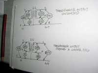
This was the technique I was alluding to. Does the fact that the center tap is grounded mean this scheme will meet code?
edit: P.S. what is the reason for secondary bonding? Is it to do with charge build-up on a floating secondary winding causing flash over?
zigzagflux said:
Pity the secondary does not have a center tap; this is a perfect application for 115-0-115V balanced power. With the electrostatic shield, you would have a fantastic noise-free power source.
This was the technique I was alluding to. Does the fact that the center tap is grounded mean this scheme will meet code?
edit: P.S. what is the reason for secondary bonding? Is it to do with charge build-up on a floating secondary winding causing flash over?
Hi all
First, I have to thank you all for contributing and especially zigzagflux for his detailed responce.
Second, I have to thank you all that, due to your seemingly non coinciding opinions, I realized that I was totally misinformed.
So I had to look deeper into the subject, read a bit more and tried to understand the whys and ifs of such an Isolation Transformer (IT).
First I had to look for an applicable code.
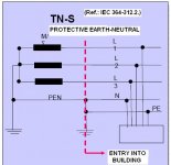
In Greece (since 2004) - as in the rest of continental Europe- the IEC 364 is adopted as the Electrical Installation Code.
(P.S. The text of the code was in Greek, so I deliberately translated it. If someone has the IEC 364 in English, please verify)
IEC 364-413.5 refers to the utilization of Galvanic Isolation.
IEC 364-413.5.1.1 : Isolation Transformers shall be per EN60742 ( 4KV isolation btn. primary & secondary for single phase transf.).
IEC 364-413.5.1.3 : Any of the energized parts of the isolated circuit shall not be connected to earth.
IEC 364-413.5.3.1 : Exposed conductive parts of the isolated circuit shall be electrically bonded but not earthed.
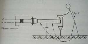
The rationale behind using an IT so connected, -as I understand it- is to brake the loop for any fault current.
There can not be an electrical continuity between any one of the bare ends of the secondary and the earth, because none is referenced to earth.
There is only capacitive coupling (thus there is restriction to the length of the lines:454m for 230Vac).
Man has to touch both bare ends of the secondary for to close such a loop(thus there is a requirement for 0.4 sec reacting fuses on the secondary).
The code restricts such a galvanically isolated installation to very specific locations and uses (and educated users).
The reason is, that control and supervision has to be exercised in order to ensure that such isolation ( see paragr. 413.5.1.3 and 413.5.3.1) will be maintained.
And just because this becomes more difficult to be attained if the isolated circuit becomes more expanded, such kind of installation is reserved for special premises and a recommendation is made for only a single component after the IT in case of severe difficulty to maintain control and supervision.
So, as I see it now (better late than never), this kind of installation with such (single secondary coil) an IT:
Should not be used for an audio rig.
Could be used in the repair and the DIY lab, provided that:
a) Nothing is or can be grounded on the secondary side and on any HOT unit connected to the secondary side (e.g. neither the "hot" radio, nor the RF signal generator or the oscilloscope).
b) All chassis (e.g. HOT radio, RF signal generator, oscilloscope) shall be connected with an electrical bonding strip to each other but not to earth.
Well, things are getting tough, don’t they?
Regards
George
First, I have to thank you all for contributing and especially zigzagflux for his detailed responce.
Second, I have to thank you all that, due to your seemingly non coinciding opinions, I realized that I was totally misinformed.
So I had to look deeper into the subject, read a bit more and tried to understand the whys and ifs of such an Isolation Transformer (IT).
First I had to look for an applicable code.
In Greece (since 2004) - as in the rest of continental Europe- the IEC 364 is adopted as the Electrical Installation Code.
(P.S. The text of the code was in Greek, so I deliberately translated it. If someone has the IEC 364 in English, please verify)
IEC 364-413.5 refers to the utilization of Galvanic Isolation.
IEC 364-413.5.1.1 : Isolation Transformers shall be per EN60742 ( 4KV isolation btn. primary & secondary for single phase transf.).
IEC 364-413.5.1.3 : Any of the energized parts of the isolated circuit shall not be connected to earth.
IEC 364-413.5.3.1 : Exposed conductive parts of the isolated circuit shall be electrically bonded but not earthed.
The rationale behind using an IT so connected, -as I understand it- is to brake the loop for any fault current.
There can not be an electrical continuity between any one of the bare ends of the secondary and the earth, because none is referenced to earth.
There is only capacitive coupling (thus there is restriction to the length of the lines:454m for 230Vac).
Man has to touch both bare ends of the secondary for to close such a loop(thus there is a requirement for 0.4 sec reacting fuses on the secondary).
The code restricts such a galvanically isolated installation to very specific locations and uses (and educated users).
The reason is, that control and supervision has to be exercised in order to ensure that such isolation ( see paragr. 413.5.1.3 and 413.5.3.1) will be maintained.
And just because this becomes more difficult to be attained if the isolated circuit becomes more expanded, such kind of installation is reserved for special premises and a recommendation is made for only a single component after the IT in case of severe difficulty to maintain control and supervision.
So, as I see it now (better late than never), this kind of installation with such (single secondary coil) an IT:
Should not be used for an audio rig.
Could be used in the repair and the DIY lab, provided that:
a) Nothing is or can be grounded on the secondary side and on any HOT unit connected to the secondary side (e.g. neither the "hot" radio, nor the RF signal generator or the oscilloscope).
b) All chassis (e.g. HOT radio, RF signal generator, oscilloscope) shall be connected with an electrical bonding strip to each other but not to earth.
Well, things are getting tough, don’t they?
Regards
George
Attachments
- Status
- This old topic is closed. If you want to reopen this topic, contact a moderator using the "Report Post" button.
- Home
- General Interest
- Everything Else
- Question about how to wire an Isolation Transformer