pooge said:
Tell that to your insurance company.
Nothing unsafe with Fig 1 esp as all the equipment plugged in is UL grounded. Just because the secondary is not grounded is not a problem as all UL approved equipment is protected in a ground fault or a reverse polarity.
Infinia
According to Gabrielson the diagram refers to isolating EMC test enclosures from noisy building grounds. A rather special case unless you intend put your audio equipment in a Farraday shielded enclosure. It is actually a good article.
Here is Gabrielson's Abstract that is associated with that diagram.
"Isolation transformers have often been considered a "cure-all" for a plethora of grounding and power line noise problems. Contrary to popular opinion, isolation transformers cannot effectively isolate a circuit from noise caused by potentials between various system and common power grounds without the intelligent use of shielding and ground design. This paper describes the theory behind the isolation transformer, its physical and electrical characteristics and its proper application."
When you assume manufacturers know what they are doing or you plug in that used piece of equipment rewired by the previous owner to defeat UL and NEC (because it was wired wrong), then change your name to Candide.
Please assemble such an arrangement in a locked room and wear a life alert medallion (help me, I've fallen and can't get up).
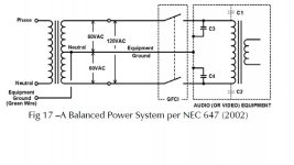
Here are the condensed requirements for a balanced power system from an article written by Jim Brown.
NEC 647, which defines the requirements for balanced power systems, places some important restrictions on both their installation and use.
1. Conductors must be sized so that the IR drop does not exceed 1% of the line voltage under a load equal to 50% of the branch circuit current rating, and so that the combined IR drop of the feeders and the branch circuit wiring does not exceed 2%.
2. A dedicated Equipment Ground conductor must be run to all equipment and each receptacle.
3. All receptacles must be protected by a GFCI.
4. The neutral must be bonded per NEC 250, and must also be connected to the grounded conductor of the circuit that feeds the system.
5. Balanced power systems are restricted to industrial and commercial occupancies.
6. All outlets “shall have a unique configuration” and must be identified using specific language called out in NEC 647.7.
7. There must be a receptacle having a grounded circuit conductor (i.e., conventional unbalanced power) within 6 ft of each receptacle for the balanced power system.
8. All lighting fixtures connected to balanced power must be specifically rated for 60/120 VAC balanced power, must “have a disconnecting means that interrupts all ungrounded conductors,” and must be permanently installed.
9. Isolated ground receptacles are permitted.
Balanced power systems are expensive, and their noise reduction capability is limited to about 10 dB. Isolated ground systems are generally a far more effective and less costly solution.
Power and Grounding for Audio and Audio/Video Systems by James Brown
Further ---
Most noise problems in audio systems stem from noise on the power system, inadequately designed cable, misunderstandings about shielding and poorly designed electronics. Poor earth grounding as a source of noise is less important than these.
For too many years, many non-engineers as well as many AV types have thought of earth grounding in terms of DC resistance rather than AC impedence. A grounding system that registers less than 1 ohm DC resistance may register a substantially higher impedence that also increases at higher frequencies. The majority of noise problems are AC phenomenae not DC.
Once a properly engineered earth ground (for the application) is established, no additional benefit is derived. You don't need the ground plane associated with an AM transmitter antenna for an audio system.
Without a quality of performance specification, how do you design a recording studio, a portable rock and roll PA, a performing arts center, a testing lab or a home reference sound system? Rule one of design is knowing what you are designing.
If I can't hear hums, buzzes, etc when the equipment is on, the disk, CD or tape is in pause, the gain of the system is set to reproduce the Berlioz Requiem dies irae movement at concert level and I put my ear within one inch of the woofer or tweeter, do I need an additional 30 dB of s/n?
I don't see the point of designing to Tempest Level 0 to achieve an adequate noise floor and shielding unless I am as paranoid as the NSC. The history of how the "Spooks" found that equipment switching, RF and acoustic noise sources could be decoded into meaningful data was fascinating. But as a goal for AV systems it is a waste of time and money. However, one does get bragging rights. Unfortunately, the techniques to achieve Tempest security levels were redacted.
Creating moving targets is a quick way of ******* off people who are serious about this.
Good luck
Chris
According to Gabrielson the diagram refers to isolating EMC test enclosures from noisy building grounds. A rather special case unless you intend put your audio equipment in a Farraday shielded enclosure. It is actually a good article.
Here is Gabrielson's Abstract that is associated with that diagram.
"Isolation transformers have often been considered a "cure-all" for a plethora of grounding and power line noise problems. Contrary to popular opinion, isolation transformers cannot effectively isolate a circuit from noise caused by potentials between various system and common power grounds without the intelligent use of shielding and ground design. This paper describes the theory behind the isolation transformer, its physical and electrical characteristics and its proper application."
When you assume manufacturers know what they are doing or you plug in that used piece of equipment rewired by the previous owner to defeat UL and NEC (because it was wired wrong), then change your name to Candide.
Please assemble such an arrangement in a locked room and wear a life alert medallion (help me, I've fallen and can't get up).
Here are the condensed requirements for a balanced power system from an article written by Jim Brown.
NEC 647, which defines the requirements for balanced power systems, places some important restrictions on both their installation and use.
1. Conductors must be sized so that the IR drop does not exceed 1% of the line voltage under a load equal to 50% of the branch circuit current rating, and so that the combined IR drop of the feeders and the branch circuit wiring does not exceed 2%.
2. A dedicated Equipment Ground conductor must be run to all equipment and each receptacle.
3. All receptacles must be protected by a GFCI.
4. The neutral must be bonded per NEC 250, and must also be connected to the grounded conductor of the circuit that feeds the system.
5. Balanced power systems are restricted to industrial and commercial occupancies.
6. All outlets “shall have a unique configuration” and must be identified using specific language called out in NEC 647.7.
7. There must be a receptacle having a grounded circuit conductor (i.e., conventional unbalanced power) within 6 ft of each receptacle for the balanced power system.
8. All lighting fixtures connected to balanced power must be specifically rated for 60/120 VAC balanced power, must “have a disconnecting means that interrupts all ungrounded conductors,” and must be permanently installed.
9. Isolated ground receptacles are permitted.
Balanced power systems are expensive, and their noise reduction capability is limited to about 10 dB. Isolated ground systems are generally a far more effective and less costly solution.
Power and Grounding for Audio and Audio/Video Systems by James Brown
Further ---
Most noise problems in audio systems stem from noise on the power system, inadequately designed cable, misunderstandings about shielding and poorly designed electronics. Poor earth grounding as a source of noise is less important than these.
For too many years, many non-engineers as well as many AV types have thought of earth grounding in terms of DC resistance rather than AC impedence. A grounding system that registers less than 1 ohm DC resistance may register a substantially higher impedence that also increases at higher frequencies. The majority of noise problems are AC phenomenae not DC.
Once a properly engineered earth ground (for the application) is established, no additional benefit is derived. You don't need the ground plane associated with an AM transmitter antenna for an audio system.
Without a quality of performance specification, how do you design a recording studio, a portable rock and roll PA, a performing arts center, a testing lab or a home reference sound system? Rule one of design is knowing what you are designing.
If I can't hear hums, buzzes, etc when the equipment is on, the disk, CD or tape is in pause, the gain of the system is set to reproduce the Berlioz Requiem dies irae movement at concert level and I put my ear within one inch of the woofer or tweeter, do I need an additional 30 dB of s/n?
I don't see the point of designing to Tempest Level 0 to achieve an adequate noise floor and shielding unless I am as paranoid as the NSC. The history of how the "Spooks" found that equipment switching, RF and acoustic noise sources could be decoded into meaningful data was fascinating. But as a goal for AV systems it is a waste of time and money. However, one does get bragging rights. Unfortunately, the techniques to achieve Tempest security levels were redacted.
Creating moving targets is a quick way of ******* off people who are serious about this.
Good luck
Chris
Attachments
Hi all
May I link you to the “Grounding and Shielding for Sound and Video” article by Philips Giddings.
It is the fifth from the bottom
It beats the subject of grounding (and shielding) in every detail to death.
It is long (37 pages) and may I commend that it does not lend itself to fast – paragraph – quote.
Man has to read it to it’s full length more than one time to clear things up.
There is a drawback though: The figures have been scanned to a low resolution, rendering embedded text almost unreadable. Man has to sketch the drawings on paper and handwrite the embedded text after reading the relative paragraphs*
*Masochistic but very effective for grasping the idea and fixing it in one's mind. It was a common practice in the past, when teachers were asking their students to sketch or draw on paper diagrams shown on the blackboard. (Extreme exercise I recall: to sketch to a different scale photos from metalography slices. I still remember the crystal lattice of iron and various steels!)
Regards
George
Hi all
Here is a good reference paper
Suppression of Powerline Noise with Isolation Transformers - Bruce C. Gabrielson and Mark J. Reimold published EMC EXPO87
http://conceptorg.com/techlibrary/PowerTechnology/Powerline_Noise_Supression.pdf
"Since most commercial instrumentation has single shielding in its power transformer, designers sometimes hope that by adding a second or primary shield (an isolation transformer), system ground problems can be eliminated. This approach often results in no benefits to the system unless all other ground paths in the instrument can be totally isolated. An isolation transformer is not a substitute for the proper shielding or grounding of individual instruments."
"Conclusion
Proper transformer design, wiring, and, above all, grounding, are the only effective means of reducing the three types of noise problems. Grounding should be controlled and use the lowest impedance path possible (i.e., bonding) to the central reference ground system to insure maximum attenuation of noise sources. To achieve the maximum protection from a transformer, not only must it be applied properly, but also the transformer should be one specially designed for isolation usage."
1) He calls for an IT to have 2 Faraday shields one for the primary and a seperate one for the secondary.
2) The primary shield is returned to the ground of the dirty power or circuit to be filtered. ( ie return the noise from whense it came)
3) The primary ckt ground or dirty power is floating and isolated from the reference ground.
4) The secondary shield is the quieter of the two and is bonded to the reference ground.
5) A dedicated reference earth ground to be connected at the equipment rack or the most sensitive intrument.
I was looking at IEC 60364, it allows for multiphase power feeds to residences with (TN) and without (IT) earth reference. The NEC code makes no exceptions which is the source of our aggressive stance in how isolation xformers are wired into power systems.
Does the IEC 60364 or other reference allow for a insulated technical ground that can be terminated at the building electrical earthing panel. This arrangement allows us a legal way to create a separate neutral on the iso transformer secondary that is not connected to the building neutral except at the building earthing panel.
The RCD used in the IT systems looks to be the functional equivalent of a GFCI but building wide. Maybe a little conversation on how this is actually implemented would be helpful.
What decision process goes into making the choice between TN and IT? Is there standardization across the EU or is there a lot of variability from country to country?
I'm sure this idea has been brought by the site Elders, but maybe it is time to include a bibliographic reference file at diyaudio.com, so we don't have to shout quite so loudly at each other.
Here is a partial bibliography that I use in one of my classes. I am always looking for more material.
Grounding
1. Technical Ground Systems vs. the Electrical Code; Philip Giddings, AES, 91st Convention, Oct., 1991.
2. Grounding Concepts and Their Implementation; Charles Atkinson, AES 97th Convention, Nov., 1994.
3. A Clean Audio Installation Guide, Allen Burdick, Benchmark Media Systems, Inc., 1997
4. Quality Grounding and Power, Warren H. Lewis & Frederic P. Hartwell, ECM Magazine, Feb., 1996.
5. Don’t Be Neutral About Grounding, Frederic P. Hartwell, ECM Magazine, Jul, 1999.
6. Guidelines for Grounding Information Technology Equipment; Information Technology Industry Council, 2/15/97.
7. Demystifying Isolated Grounding Systems, Part 1 & 2: Ken Michaels, ECM Magazine, Mar, 1999.
8. Broadband Grounding Practices, Farrell Becker, Syn-Aud-Con Tech Topic, Vol. 29-4, Fall, 2001.
9. CERN Chapter 2: Grounding
10. IEEE – EMI Emissions of Modern PWM AC Drivers
11. How’s and Why’s of Isolated Grounding, Thomas M. Grucz, Seventh International Power Quality Conference, Oct., 1993.
12. Ground – A Path for Current Flow, Henry W. Ott, Bell Labs, EMC Journal, Jan-Mar., 1983
13. Grounding and Shielding for Sound and Video, Philip Giddings, Engineering Harmonics, Inc., 1996
Power
1. Three Phase Power Source Overloading Caused by Small Computers and Electronic Office Equipment; Information Technology Industry Council, Jun., 1987.
2. An Overview of IEEE 1100: The Emerald Book; Thomas M. Gruzs, ECM Magazine, Feb., 1996.
3. Suppression of Powerline Noise with Isolation Transformers; Bruce C. Gabrielson & Mark J. Reimold, EMC Expo 87, May, 1987.
4. ITI Safe Power Curve Application Note; Information Technology Industry Council.
5. Understanding IG Receptacles; Warren H. Lewis, ECM Magazine, Jan., 1996.
6. Understanding IG Wiring; Warren H. Lewis, ECM Magazine, Feb., 1996.
7. UPS Topologies and Standards; MGE UPS Systems, Nov., 1999.
8. Electrical Power Supply and Distribution, US Army/Air Force, TM 5-811-1/AFJMAN 32-1080, Feb., 1995.
9. Troubleshooting Power Problems, Neil A. Muncy, Pro AV Magazine, 10/27/04
Shield Current Induced Noise and Pin One Grounding Problem
1. Common-mode to Differential-Mode Conversion in Shielded Twisted-Pair Cables; Jim Brown & Bill Whitlock, AES 114th Convention, Paper 5747, Mar., 2003.
2. An Easily Implemented Procedure for Identifying Potential Electromagnetic Compatibility Problems in New Equipment and Existing Systems – The Hummer Test; John Windt, AES 97th Convention, Preprint 3918, Nov., 1994.
3. Noise Susceptibility in Analog & Digital Signal Processing Systems, Neil A. Muncy, AES 97th Convention, Preprint 3930, Nov., 1994
Transmission Lines, Wire and Cable
1. The Basics of Transmission Lines; Dennis J. Ramsey, Dec., 1998.
2. A Transmission line calculator, Version 0.3; Kevin Schmidt.
3. Telecommunications Wiring, 3rd Edition, Chapter 1; Clyde Herrick, Prentice Hall, ISBN: 0130286966; Published: Dec 1, 2000; Copyright 2001.
4. Characteristic Impedance of Cables at High and Low Frequencies; The Engineering Department Belden Electronics Division.
5. Recommendations for Home Theater and High-End Audio, Belden Electronics Division.
6. Coaxial Cables and Applications; Martin J. Van Burgt, Belden Electronics Division, 2003.
7. Conduit Fill and Ampacity Calculations for Low-voltage Cables; Mark Ode, Electrical Contractor, Mar., 2000.
8. High Definition Cabling and Return Loss; Stephen H. Lampen, Martin J. Van Der Burgt, & Carl W. Dole, SMPTE Journal, Jan., 2001.
9. How Wire Fails; Stephen H. Lampen, SMPTE 1997 Convention, Jul, 1997
10. Tune In to the Requirements of Art. 820; Mike Holt, ECM Magazine, Dec., 2003
11. Speed of “Electricity”; Bill Beaty, 1996.
12. Wireless Microphones and the Audio Professional; Jim Brown, ASG, 2001.
13. Conduit Size Calculator, Dick Trump, Triad AV Services
Perception and Distortion
1. Rules of the Game; James Boyk, Hi-Fi News and Record Review (England), Jan., 1983, copyright 1997.
2. The Psychology of Multichannel Sound; J Robert Stuart, Meridian Audio.
3. Perception Issues in Multi-channel Environments; J Robert Stuart, Meridian Audio.
4. The Concept of Distortion, Richard C. Heyser, AES-LA, Ambassador College, 1980.
5. Comparison of Non-Linear Distortion Measurement Methods; Richard C. Cabot, Audio Precision,
6. Tubes vs. Transistors – Is There an Audible Difference?; Russel O. Hamm, AES Journal, Vol. 21-4, May, 1973.
7. Amplifier Topologies
8. Life Above 20 KHz!, James Boyk, Caltech, 1997.
Other Text Books
Audio System Design and Installation, Phillip Giddings, SAMS, 1990
Sound System Engineering, 2nd Edition, Don and Carolyn Davis, SAMS, 1987
Handbook for Sound Engineers, 3rd Edition, Glen Ballou, Butterworth-Heinemann, 2002
Sound Reinforcement Handbook, 2nd Edition, Leonard, 1989
Noise Reduction Techniques in Electronic Systems, 2nd Edition, Henry W. Ott, Wiley, 1988
1100-1999 EMERALD BOOK IEEE Recommended Practice for Powering and Grounding Electronic Equipment, IEEE, Emerald Book 1999,
NECA 409-2002, Recommended Practice for Installing and Maintaining Dry-Type Transformers (ANSI)
NECA/BICSI 568-2001, Standard for Installing Commercial Building Telecommunications Systems (ANSI)
NECA Guide to Installing Communications Systems
2002 National Electrical Code, National Fire Protection Association, Quincy, Ma.
Understanding Electric Power Systems: An Overview of the Technology and the Marketplace, Jack Casazza, Frank Delea, IEEE/Wiley, 2003
Electromagnetics : History, Theory, and Applications, Robert S. Elliott, IEEE/Wiley, 1999
Grounding and Shielding Techniques, 4th Edition, Ralph Morrison, IEEE/Wiley, 1998
chris
cbcassell said:The NEC code makes no exceptions which is the source of our aggressive stance in how isolation xformers are wired into power systems.
Maybe it's time the NEC gets up to speed. I don't know but the only thing I can think of is legacy support for olden time products like AC/DC radio's... you know the ones with the 120 neutral tied to the chassis.
I just have a problem with some people citing NEC requirements for a device/product which is not in it's bailiwick.
Hi all
In my early posts in this thread I clearly raised the flag for help and advise regarding safety of use and noise immunity of an isolation transformer. Then participant(s) responded promptly that safety is the main issue and provided references.
Me, from my part started to feel uncomfortable, because I realized that I am lucking the required knowledge.
Now think of this: A man who has the misfortune to see a lot of unsafe installations and who has access to statistics about accidents induced by electricity misuse, visits the site where a poster (me) presents an electrical connection scheme which under some (say very rare) circumstances can raise a safety issue or a hazard.
This man has the following options:
1. To let the poster take his chances.
2. To warn loud and clear about the (distant) danger.
3. To insist in warning when the poster ignores his warning.
4. To provide data when the poster is not able to understand the content of the warning.
5. To leave the site, leaving the poster to his own devices after understanding that his intervening is not welcome.
Talking from the posters side, I am glad that this man chose the uncomfortable 2, 3 and 4 options. He hasn't earn some extra money, he hasn't got a medallion , yet he has to defend his myopic posts ( the term magnifying glass posts would have been a fair one).
Thank you dear man
Regards
George
- Status
- This old topic is closed. If you want to reopen this topic, contact a moderator using the "Report Post" button.
- Home
- General Interest
- Everything Else
- Question about how to wire an Isolation Transformer