come on folks!! This is an equipment application not a building wiring question. If any codes apply here they would be safety issues addressed by UL/CSA/TUV VDE.
The only way to wire it and still have an ISOLATION transformer is shown in fig 1. Remember at the primary the N is electrically connected to E at the entry panel. If you connect the secondary to E again you have completely eliminated the function. Not to mention any CM noise reduction you are tring to achieve if any.
Anyway for devices shown here http://www.surplussales.com/transformers/IsolationXmers-2.html
The cases are earth grounded and passed through to the output isolated.
Richard Ellis said:I would bet the wiring of the output of your IT is currently correct. Did you notice your measurements on the secondary don't add up to your 229Vac?
Think how the circuit works as in electron flow. The measurements from Live or Nuetral to Earth are capacitatively(?) coupled...I think that your DVOM puts such a light load on the circuit...that you can get any reading. I would bet if you loaded the circuit just a little you won't read any voltage at all. Wouldn't be baffling if you had a cheap meter & you tested both 'L' & 'N' ...and it gave you no readable voltage?
You should be able to pull down that reading with microamps & the voltage would drop.to nothing.
___________________________________________Rick.............
Hi qpapaq
The secondary voltages you are reading are due to interwinding capacitances between both of your transformer windings and other parasitic/added capacitances to earth forming an AC voltage divider. For medical grade and high common mode isolation transformers the 2 windings are physically seperated ie wound on seperate sides to reduce this "AC leakage" effect. As Rick pointed out this should go away as your load is increased. Idea >You could add a common mode line filter or added Y caps to the secondary to swamp out the interwinding leakage cap.
Iain McNeill said:Does the fact that the center tap is grounded mean this scheme will meet code?
edit: P.S. what is the reason for secondary bonding? Is it to do with charge build-up on a floating secondary winding causing flash over?
A grounded center tap, balanced power system is permitted with certain restrictions. The most significant requirement to DIY'ers in simplistic form is the balanced system should only feed the audio rack, no other equipment. You cannot plug in a cord connected lamp, for instance; just that audio gear.
There are a number of reasons to bond the secondary. One that an ungrounded system will tend to exhibit transient overvoltage problems. From IEEE Std 242-7.2.5:
If this ground fault is intermittent or allowed to continue, the system could be subjected to possible severe overvoltage to ground, which can be as high as six or eight times phase voltage. This can puncture insulation and result in additional ground faults. These overvoltage are caused by repetitive charging of the system capacitance, or by resonance between the system capacitance and the inductances of equipment in the system.
Granted, this primarily occurs on traditional 480V three phase systems, but it is one of the reasons the Code added in the requirement to bond in almost all systems 50-1000V.
Another reason that comes to mind is that in the event of an equipment ground fault (by far the most common type of electrical equipment failure), the response to a grounded system will usually be operation of the upstream overcurrent device (trip the breaker). This is a good thing, as it prevents the possibility of a device with failed insulation from continuing normal operations without the user knowing. On a practical safety level, the average Joe User could be harmed by failure of this device in any number of ways.
gpapag said:zigzagflux
Ref post#14 puzzle
the GFCI on the primary will not trip with any of the 3 occurancies on the secondary.
Exactly, well done. Not that it matters, but I would add that in #3, the 15A breaker would probably trip, but NEVER the GFCI.
Why do I bring this question up? Because those who continue to insist that #1 is the way to go do not understand how ground currents flow:
infinia said:Remember at the primary the N is electrically connected to E at the entry panel. If you connect the secondary to E again you have completely eliminated the function.
If I 'completely eliminated' the isolating function of the transformer, then why does the GFCI never trip? Even seasoned electricians have difficulty understanding this issue. The answer is that the transformer has indeed done all the isolating necessary; the only other benefit one may be able to obtain (legally) is 115-0-115 balanced power.
zigzagflux said:
Exactly, well done. Not that it matters, but I would add that in #3, the 15A breaker would probably trip, but NEVER the GFCI.
Why do I bring this question up? Because those who continue to insist that #1 is the way to go do not understand how ground currents flow:
If I 'completely eliminated' the isolating function of the transformer, then why does the GFCI never trip? Even seasoned electricians have difficulty understanding this issue. The answer is that the transformer has indeed done all the isolating necessary; the only other benefit one may be able to obtain (legally) is 115-0-115 balanced power.
Your case number 3 the GFCI is not designed to trip because there are no abnormal earth currents flowing in that simple example of a L-N short. I don't think you understand the purpose of an isolation transformer and you never addressed the cause of the OP original Q. Sure grounding the secondary will fix it but then it defeats the whole purpose of the thing.
zigzagflux said:
Why do I bring this question up? Because those who continue to insist that #1 is the way to go do not understand how ground currents flow:
Hmm that is a huge underestimation on your part. Not only in my case but most others in this thread as well. But you go ahead an explain away.
yet again one of the bad sides
of our forum ......
often to a simple question in the forum you may find so much theory that will be enough to take you to the moon except the actuall answer .....
Let us also not forget that half of the word application often comes from the word aspect ......
may things that apply in electrical installation laws do not apply for audio and visa versa
earth loops for example may exist a million times in our home and will effect nothing as long as the load is simple lamps ..... but if the load is audio earth loops can create a huge mess )
george .....
i would be very happy to know what i asked above regarding the original post and what made you start this search ....
Re: yet again one of the bad sides
It would not be so bad if it was theory based. What really gets my dander is doggedly held dogma. or to the guy with only a hammer everything appears as a nail head.
sakis said:of our forum ......
often to a simple question in the forum you may find so much theory that will be enough to take you to the moon except the actuall answer .....
It would not be so bad if it was theory based. What really gets my dander is doggedly held dogma. or to the guy with only a hammer everything appears as a nail head.
ZIGzigzagflux said:
Emphatically wrong!! The transformer is classified as a separately derived system, and it is required to ground one conductor. This conductor then becomes named the neutral. There are no exceptions to this;
you are wrong.
One must never connect the Neutral to Safety Earth.
ANDRW IS RIGHT ....
ANDREW IS RIGHT ..... there is got to be something that you either tell wrong or understand wrong .....
unless what you state is about to take place in the distribution box of the buliding before ( but really before ) everything else and very close to the electrical systems main ground
this is the tecnique used in our country some 34-40 years ago now days grounds are all diferential
AndrewT said:ZIG
you are wrong.
One must never connect the Neutral to Safety Earth.
ANDREW IS RIGHT ..... there is got to be something that you either tell wrong or understand wrong .....
unless what you state is about to take place in the distribution box of the buliding before ( but really before ) everything else and very close to the electrical systems main ground
this is the tecnique used in our country some 34-40 years ago now days grounds are all diferential
Neutral is connected to safety earth at the service entrance, and usually not connected to earth at another point.
However, like said above, the transformer is classified as a separately derived system. Therefore, one of the transformer leads must be connected to earth to become a neutral.
However, like said above, the transformer is classified as a separately derived system. Therefore, one of the transformer leads must be connected to earth to become a neutral.
this is absolutelly wrong
......
the transformer in the out put preserve the phase arengement due to winding phase ( though since this is inductive does not have the same behavior as the phase coming out of your socket )
then on the other hand if simply ground one of the two leads there is no point to have such a transfromer any way ....the idea of this trafo is that the output is "floating" and has no connection anywhere
do you have any idea on what is going to happen if after the transformer a surge protector exists in any of the devices ????
probably explosion in case something goes wrong .... especially if we talk about aserious surge that would possibly find its way through this connection and then return from the so called neatural lead back to yor device .....big kabbboooom
cause it will be easier to find its way back to the device than go back where the real ground is IE way too far away and with way too small cables .....
think ...... its the same easy like 1+1=2
This is not absolutely wrong. Unless you have a situation in which a floating source is allowed, you MUST have a neutral.
And just where is this supposed "explosive" surge coming from? The transformer itself will limit surges coming from the AC supply. Further, any surge protector should be placed at the AC source, i.e., distribution box, to be its most effective.
Your authoritative responses do not seem to be that authoritative.
If a supply requires a neutral, there is no neutral on the secondary unless it is bonded to ground.
Okay, guys, this is really not that difficult of an issue. The transformer changes everything. It's that simple. It breaks the continuity of the ground current path. If the transformer were removed from the trivia questions 1-3, you WOULD have the GFCI tripping in 2 and 3, and possibly in 1. But it would NEVER trip with the transformer installed. This is the isolation that is occurring. The fact that the secondary winding is referenced to earth does not remove the benefits of the transformer.
There is apparently a stink being raised about the desire to float the secondary winding, in order to obtain 100% 'isolation'. While there is the potential to allow the rest of the system to find its own ground elsewhere, if at all, the US Code (again, I make no claims about the Code in other countries) simply does not permit it. You absolutely must plug in your cord-connected CDP, amplifier, preamp, etc to a power source that has a hot and grounded conductor (neutral). This may bother many people, as they WANT to plug their equipment into a floating system; but it breaks Code. At least have the guts to admit you choose to break the Code, and will float your secondary, claiming all the benefits of a floating system. And maybe you do get more benefit; I have never claimed there is no benefit to this (although I would pursue a grounded balanced scheme over a floating scheme any day). The ire is not over benefit, it's over legality.
You can claim all day long that the transformer does not isolate unless the winding is left floating, but it just isn't permitted. Period. Go ahead and call it dogma, infinia; you seem to overuse that word when threatened. Pick a new one.
You absolutely insist on a floating system? Put the transformer inside the gear. Hello, your CDP and amplifiers already have this. Remove the secondary bond there. But you want to install a transformer and plug multiple devices into it? It must be a separately derived grounded source.
For those of you who care about legality, I would present the following: I am a state licensed and practising Professional Engineer. I didn't say I went to college and got a degree (although I do have one). I am licensed to give advice in these matters, and have been for years. Electrical contractors come to us for advice in grounding, testing, transformers, regulation, and generation of residential, commercial, industrial, and utility power systems. I am not an audiofool; you can choose who you want to believe.
So, here's what the Code has to say (from a US perspective):
Pretty straightforward. It is often that I hear people claim the Code stops its jurisdiction at your power panel, but sorry, it goes much further than that. It even covers cord and plug connected equipment.
Now these are of course abridged references, as there are some missing points, but I have only included the items of interest to the subject matter. Also, note the 150V requirement; in the US most all utilization equipment is 120V. I understand other countries use 230V as their standard; I would expect their Codes to address this with the 150V replaced by 250V; one will have to consult their own country.
In case you want to claim this only applies to the service entrance, those requirements are specified elsewhere:
I have provided this reference for two purposes: one, the fact that our isolation transformer constitutes a separately derived system means these requirements apply to it, and therefore bonding is required (not optional). Second, it shows the lack of understanding to the generic "never bond the neutral downstream of the service" idea. Neutrals are constantly being legally bonded downsteam of the service entrance. This occurs every time you go through a transformer, and the Code demands it. Once I have bonded my transformer neutral, I am not permitted to add additional neutral bonds downstream of this first bond. Unless I feed another transformer, of course. Then I need a new bond.
Now for the bad news. It would appear that the average residential Joe is not permitted to install balanced power systems. This might actually be a good idea, since I can see how much confusion people have on this subject, and the propensity for a good design to get abused.
So take it for what it is. My conclusion would be you can all choose to do what you want, but don't claim you are being legal (in America) in any way shape or form. Sometimes I break the speed limit when I'm late for work; I admit it. But I don't claim that there is no law of a speed limit, or that those who insist you can get a ticket from a police officer for breaking it are just holding to dogma. I may also strongly disagree that the speed limit on a particular road should be 25mph; maybe I think 35mph is much more reasonable. I am free to drive 35, but that doesn't mean it's right. If you disagree with the law, then say you disagree. Don't tell me the law doesn't exist.
If you need pictures to see the proper way of handling things, I think this is a pretty good reference:
http://www.exactpower.com/assets/pdfs/theTRUTH.pdf
Especially look at pages 26 and 27.
There is apparently a stink being raised about the desire to float the secondary winding, in order to obtain 100% 'isolation'. While there is the potential to allow the rest of the system to find its own ground elsewhere, if at all, the US Code (again, I make no claims about the Code in other countries) simply does not permit it. You absolutely must plug in your cord-connected CDP, amplifier, preamp, etc to a power source that has a hot and grounded conductor (neutral). This may bother many people, as they WANT to plug their equipment into a floating system; but it breaks Code. At least have the guts to admit you choose to break the Code, and will float your secondary, claiming all the benefits of a floating system. And maybe you do get more benefit; I have never claimed there is no benefit to this (although I would pursue a grounded balanced scheme over a floating scheme any day). The ire is not over benefit, it's over legality.
You can claim all day long that the transformer does not isolate unless the winding is left floating, but it just isn't permitted. Period. Go ahead and call it dogma, infinia; you seem to overuse that word when threatened. Pick a new one.
You absolutely insist on a floating system? Put the transformer inside the gear. Hello, your CDP and amplifiers already have this. Remove the secondary bond there. But you want to install a transformer and plug multiple devices into it? It must be a separately derived grounded source.
For those of you who care about legality, I would present the following: I am a state licensed and practising Professional Engineer. I didn't say I went to college and got a degree (although I do have one). I am licensed to give advice in these matters, and have been for years. Electrical contractors come to us for advice in grounding, testing, transformers, regulation, and generation of residential, commercial, industrial, and utility power systems. I am not an audiofool; you can choose who you want to believe.
So, here's what the Code has to say (from a US perspective):
90.2 Scope
(A) Covered. This Code covers the installation of electrical conductors, equipment, and raceways; signaling and communications conductors, equipment, and raceways; and optical fiber cables and raceways for the following:
(1) Public and private premises, including buildings structures, mobile home, recreational vehicles, and floating buildings.
Pretty straightforward. It is often that I hear people claim the Code stops its jurisdiction at your power panel, but sorry, it goes much further than that. It even covers cord and plug connected equipment.
250.20 Alternating-Current Systems to be Grounded: Alternating –current systems shall be grounded as provided for in 250.20(A),(B),(C),or (D)
(B) Alternating-Current Systems of 50 Volts to 1000 Volts. Alternating-current systems of 50 volts to 1000 volts that supply premises wiring and premises wiring systems shall be grounded under any of the following conditions:
(1) Where the system can be grounded so that the maximum voltage to ground on the ungrounded conductors does not exceed 150 volts.
(D) Separately Derived Systems. Separately derived systems, as covered in 250.20(A) or (B), shall be grounded as specified in 250.30.
Now these are of course abridged references, as there are some missing points, but I have only included the items of interest to the subject matter. Also, note the 150V requirement; in the US most all utilization equipment is 120V. I understand other countries use 230V as their standard; I would expect their Codes to address this with the 150V replaced by 250V; one will have to consult their own country.
In case you want to claim this only applies to the service entrance, those requirements are specified elsewhere:
So the 250.20 reference applies anywhere in the premises wiring system.250.24 Grounding Service-Supplied Alternating-Current Systems
Here the term neutral conductor would need some explanation, but fundamentally it would refer to the center tap.250.26 Conductor to be Grounded – Alternating-Current Systems. For ac premises wiring systems, the conductor to be grounded shall be as specified in the following:
(1) Single phase, 2-wire – one conductor
(2) Single phase, 3-wire – the neutral conductor
250.30 Grounding Separately Derived Alternating-Current Systems
(A) Grounded Systems. A separately derived ac system that is grounded shall comply with 250.30(A)(1) through (A)(8). A grounding connection shall not be made to any grounded circuit conductor on the load side of the point of grounding of the separately derived system except as otherwise permitted in this article.
(1) System Bonding Jumper. An unspliced system bonding jumper in compliance with 250.28(A) through (D) that is sized based on the derived phase conductors shall be used to connect the equipment grounding conductors of the separately derived system to the grounded conductor. This connection shall be made at any single point on the separately derived system from the source to the first system disconnecting means or overcurrent device, or it shall be made at the source of a separately derived system that has no disconnecting means or overcurrent devices.
I have provided this reference for two purposes: one, the fact that our isolation transformer constitutes a separately derived system means these requirements apply to it, and therefore bonding is required (not optional). Second, it shows the lack of understanding to the generic "never bond the neutral downstream of the service" idea. Neutrals are constantly being legally bonded downsteam of the service entrance. This occurs every time you go through a transformer, and the Code demands it. Once I have bonded my transformer neutral, I am not permitted to add additional neutral bonds downstream of this first bond. Unless I feed another transformer, of course. Then I need a new bond.
647.3 Sensitive Electronic Equipment: Use of a separately derived 120 volt single phase 3-wire system with 60 volts on each of two ungrounded conductors to a grounded neutral conductor shall be permitted for the purpose of reducing objectionable noise in sensitive electronic equipment locations, provided the following conditions apply:
(1) The system is installed only in commercial or industrial occupancies.
(2) The system’s use is restricted to areas under close supervision by qualified personnel.
(3) All of the requirements of 647.4 through 647.8 are met.
Now for the bad news. It would appear that the average residential Joe is not permitted to install balanced power systems. This might actually be a good idea, since I can see how much confusion people have on this subject, and the propensity for a good design to get abused.
So take it for what it is. My conclusion would be you can all choose to do what you want, but don't claim you are being legal (in America) in any way shape or form. Sometimes I break the speed limit when I'm late for work; I admit it. But I don't claim that there is no law of a speed limit, or that those who insist you can get a ticket from a police officer for breaking it are just holding to dogma. I may also strongly disagree that the speed limit on a particular road should be 25mph; maybe I think 35mph is much more reasonable. I am free to drive 35, but that doesn't mean it's right. If you disagree with the law, then say you disagree. Don't tell me the law doesn't exist.
If you need pictures to see the proper way of handling things, I think this is a pretty good reference:
http://www.exactpower.com/assets/pdfs/theTRUTH.pdf
Especially look at pages 26 and 27.
That would be fine, but as always, there are requirements to doing that as well. Not to make this too much of a Code class, but you have to use a receptacle listed for isolated ground service, as the construction is different.
Also, you still have to ground the enclosure(s), which in your case of wanting a completely isolated ground for your equipment, would require a secondary grounding means i.e. the bare conductor in NM cable or the armor of AC cable. MC cable would be insufficient as a grounding means, as the sheath is not recognized for fault current.
Also, you still have to ground the enclosure(s), which in your case of wanting a completely isolated ground for your equipment, would require a secondary grounding means i.e. the bare conductor in NM cable or the armor of AC cable. MC cable would be insufficient as a grounding means, as the sheath is not recognized for fault current.
I agree with Zigzagflux. While I am not an EE nor am I licensed, I do create power systems design recommendations for large and small AV systems that are to be reviewed and conformed to local electrical codes by licensed electrical engineers.
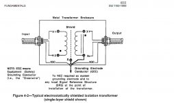
The NEC codes are specific, as are the IEEE Emerald Book recommendations. The primary purpose of grounding is safety. Any advantage beyond safety is a bonus. I have included an IEEE diagram that shows the recommended wiring of a single phase isolation transformer. Any other approach is leaving oneself open to a wrongful death lawsuit.
What happens if someone touches a device with no safety ground connected to your floating power supply and simultaneously touches a device that is properly grounded to the building power system?
Chris
Attachments
OK THEN
PLEASE SHOW AS SCHEMATIC ON HOW A 3 PHASE 380V ISOLATION TRAFO IS THEN WIRED ???????
CAUSE IF WHAT YOU SAY IS CORRECT THIS CANNOT BE DONE AS LONG AS ONE OF THE LEADS ON EACH WINDING IS ATTACHED TO GROUND THEN YOU CANNOT GET 380 VOLT TRIANGLE BUT ONLY STAR 230 ......
BY THAT .....if the output of a 3phase trafo can be floating then i dont see any reason why not cannot be floating when the trafo is one phase ....
ALL THIS THREAD IS GONE TO MARS I THINK ....
cbcassell said:I agree with Zigzagflux. While I am not an EE nor am I licensed, I do create power systems design recommendations for large and small AV systems that are to be reviewed and conformed to local electrical codes by licensed electrical engineers.
The NEC codes are specific, as are the IEEE Emerald Book recommendations. The primary purpose of grounding is safety. Any advantage beyond safety is a bonus. I have included an IEEE diagram that shows the recommended wiring of a single phase isolation transformer. Any other approach is leaving oneself open to a wrongful death lawsuit.
What happens if someone touches a device with no safety ground connected to your floating power supply and simultaneously touches a device that is properly grounded to the building power system?
Chris
PLEASE SHOW AS SCHEMATIC ON HOW A 3 PHASE 380V ISOLATION TRAFO IS THEN WIRED ???????
CAUSE IF WHAT YOU SAY IS CORRECT THIS CANNOT BE DONE AS LONG AS ONE OF THE LEADS ON EACH WINDING IS ATTACHED TO GROUND THEN YOU CANNOT GET 380 VOLT TRIANGLE BUT ONLY STAR 230 ......
BY THAT .....if the output of a 3phase trafo can be floating then i dont see any reason why not cannot be floating when the trafo is one phase ....
ALL THIS THREAD IS GONE TO MARS I THINK ....
I Can Link You
to as many pages of isolation transformers ( european standards i presume ) that simply have a safety ground for the device and then 2 leads for in and 2 leads for out .......
here is one .... http://www.atman.gr
it doesnt say anywhere that you need to connect any of the leads to the ground
( havent figered this yet but i think that also a tie like that will trigger the mains protection and safety relay that we have in europe ..... do you have the same whee you come from ??? )
- Status
- This old topic is closed. If you want to reopen this topic, contact a moderator using the "Report Post" button.
- Home
- General Interest
- Everything Else
- Question about how to wire an Isolation Transformer