Hello everyone! I am in the mists of building a joule thief. In short a "joule thief" is a low voltage power supply for powering leds. A good explanation of it is posted on hack a day.com (here is the link http://hackaday.com/2007/10/10/joule-thief-led-driver/#comment-62214 .) So I made a large mouser order and got all the stuff I believe i need. I am trying to run the circuit on .2v so this is a specific version of a joule thief.
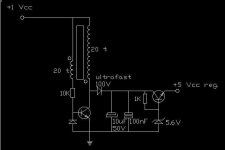
Could anyone help me read this diagram. http://wiki.waggy.org/dokuwiki/electronics/joulethief (Very Low Input Voltage Step-up Regulated Power Supply) It is written with key board symbols and i am having trouble deciphering it.
Will post pictures as i build!
thanks!
Could anyone help me read this diagram. http://wiki.waggy.org/dokuwiki/electronics/joulethief (Very Low Input Voltage Step-up Regulated Power Supply) It is written with key board symbols and i am having trouble deciphering it.
Will post pictures as i build!
thanks!
You may have had not many replies, because his schematics are VERY unclear.
ASCII schematics are sloppy, and unreadable. I can't even clearly make out the symbols, and where the diode is suppose to be!
If the guy could make a webpage, I don't see why he can't at least take a good hour or so and make a handmade readable schematic in MSpaint to put on it!
It appears to oscillate using a transformer which steps up the voltage to drive an LED.
Here's an idea:
Try making your own. Make an oscillator from one or two transistors and use a transformer of some type to step-up the voltage. Just look online for typical oscillator or astable multivibrator schematics, and drive a transformer with it. You will need at least 1.2V or more to drive your circuit, because silicone transistors on average drop nearly 0.7V just to turn on, so 0.2V is not near enough.
I have done something like that: http://bigclive.com/joule.htm
It works good with 0.5V input, using a normal silicon transistor, or a digital transistor like DTA114... small package and base resistor inside...
At the collector of the transistor, you can place a scottkly diode and cap to ground, and you have a stepped-up dc voltage. add a zener diode, and something else, and you have a regulated dc voltage.
nice
Thanks for all the hlp guys!
I have to certainly agree about the lack of clarity on with that web diagram. I had even emailed the author to try to get him to clarify - but got no response.
I Was intrigued by his posted circuit because of its ability to drive with such low voltages. 0.2 volts is not very much.
You guys are absolutely correct tho - i should experiment myself with the circuit to see what i can do with it. Will try your suggested diagram and get back to you guys!
For 0.2V, you have to use a germanium transistor. They are obsolete, difficult to find, and with very poor voltage and current characteristics... good luck.
Another thing: to obtain a relative small current on 5V rail (example 10mA), you have to drain a lot of current from 0.2V supply (about 0.5A, or more). It's better to use an over-sized transistor...
Another thing: to obtain a relative small current on 5V rail (example 10mA), you have to drain a lot of current from 0.2V supply (about 0.5A, or more). It's better to use an over-sized transistor...
- Status
- This old topic is closed. If you want to reopen this topic, contact a moderator using the "Report Post" button.
- Home
- General Interest
- Everything Else
- Joule Thief - LED low voltage Power supply - With pictures