I'm looking for a way to recognise when a green laser pen "gun" is shone at a "target" circuit. If any of you have ever been to anywhere like Laser Quest, Megazone or Quasar, you'll know what I'm talking about.
The first idea I've come up with is an array of LDRs and transistors tuned with pots to the point where only the high intensity of the laser turns it on. The problem is that this has to work outside and not be tripped by car headlights and suchlike. Furthermore, this must operate correctly at distances over 800m.
The best solution I can think of is to use long/medium wave radio and a tone detector to enable the LDR target receiver. The "gun" would turn on the laser and transmit a tone over radio. The "target" would receive this signal and switch on the LDR circuitry, allowing the target to register the shot.
Any circuit ideas?
If you can modulate the laser it's easy to detect it. That's how almost all commercial conveyor line sensors and such avoid being tripped by ambient light, including modulations from fans and and headlights and such. If you can't modulate the laser your chances of success are much lower. You'll have to resort to narrow band optical filtering to reduce sensitivity to other light sources, and getting the trip level right will be near impossible unless the system is hard mounted with fixed alignment.
I'd be using a standard green laser pen with a relay hooked up to the switch, so no modulation. It's not really an issue though as long as I'm using some other form of enable signal. If the target LDR is only switched on whilst it is receiving the radio signal (i.e. whilst the "gun" fires - a 300ms period at most) it is very unlikely to get hit with a enough light to cause it to be tripped. This equipment will be used at night in rural and village areas, so there will be very few cars around. I think the trick will be to find an LDR that has a very low sensitivity, or one that does not reach max/min resistance until a very bright light hits it.
As far as IR for the shot goes, I don't think it'd work over distances of 800m. To get the distance I'd need very bright IR LEDs, but then I'd loose all precision - I don't want to have the sensor tripped if I miss them by 2 inches, let alone 2ft.
The reason I suggested using AM radio for the enabling signal is that it's pretty easy to build a portable battery powered AM transmitter that gets ranges of 1km, and as long as I'm only transmitting short beeps on an unused frequency there's no licensing issue.
Anyone know of a circuit I could use for an AM transmitter? I've found plenty of suitable FM ones (this one in particular, using the larger PCB option), but not any AM ones. FM is much more highly regulated and I don't want to get caught spamming local FM radio with bleeps.
What makes you think you can't get IR lasers? And by insisting on not having modulation (why not have your laser hooked to a modulation circuit hooked to your relay hooked up to the switch?) you're inventing a new set of problems.
If you do go this way, remember to put a green filter over the LDR to reduce the odds of it being tripped by other random bright things.....obviously, anything bright and with enough green in the spectrum will trip it anyway.
If you do go this way, remember to put a green filter over the LDR to reduce the odds of it being tripped by other random bright things.....obviously, anything bright and with enough green in the spectrum will trip it anyway.
Another thought - LED's make quite a good narrow spectrum light detectors, if you need a very small target. A green LED typically detects light best at about 560nm, and adequately well at the typical "green" laser wavelength of 532nm.
Of course, the currents are on the order of microamps, so you'd need an amplifier, but audio grade cleanliness is hardly required here.
Of course, the currents are on the order of microamps, so you'd need an amplifier, but audio grade cleanliness is hardly required here.
TheSeekerr said:Another thought - LED's make quite a good narrow spectrum light detectors, if you need a very small target. A green LED typically detects light best at about 560nm, and adequately well at the typical "green" laser wavelength of 532nm.
Of course, the currents are on the order of microamps, so you'd need an amplifier, but audio grade cleanliness is hardly required here.
I'd be interested to see an example of this. Transistor amp or opamp? Would it work if I put a group of LEDs in parallel? It'd be very cheap and easy to put an array of 10x10 green LEDs together, and it'd be a perfectly sized target.
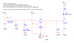
I've simulated a simple latch circuit for my target - image attached. The reset key is literally a key switch (this will be a paintball style game - one hit and you're dead) so that players cannot turn themselves back on. The alive signal LED will actually also be linked to the attached gun's power, disabling the player completely until the key is used to reset them.
Attachments
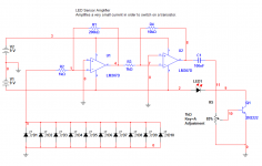
Simulated a simple amplifier based on opamps that can effectively switch on a transistor with a very small current input. Schematic attached. I've simulated the circuit by swapping the LED array out for a fixed current source of 2.5uA and it seems to work perfectly.
EDIT:
Just as a side-note, the lasers I've opted for are 532nm with a power of 30mW. Only £20 each too!
EDIT:
Just as a side-note, the lasers I've opted for are 532nm with a power of 30mW. Only £20 each too!
Attachments
I'm busy for a couple of days so I'll not have chance to get to an electronics store to buy a few bits - I'm all out of opamps. Actually I might see if my dad has any in the shed. Anyhoo, I'll whack it together on a bit of veroboard and see how it goes. I'll use my halogen spotlight and a green filter from some old disco equipment to test the results... until the lasers arrive that is!
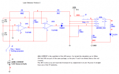
Just a quick question regarding my amplifier - I can imagine that if a lot of the LEDs were having lasers fired at them, the current produced would be closer to 25uA (ten times the original 2.5uA) - would this cause problems? I guess it depends on the transistor I use, but there are likely to be limitations on the kind of voltage I can put through C1 and onto Q1's base. If my calculations are correct (probably not, I did them in a rush) an input current of 25uA will likely produce a 45V output.
I think my best bet would be to initially remove Q1 and the LED, and replace them with a 1K resistor going to ground, then measure the voltage across the resistor in order to get an idea of the output voltage. Do you agree?
erm....it seems to me that into a high impedance load, they'll behave more like voltage sources, so it shouldn't cause a problem, since a voltage in parallel is still just a voltage? Just so long as your amplifier doesn't clip and latch to the rails or anything ugly like that.
- Status
- This old topic is closed. If you want to reopen this topic, contact a moderator using the "Report Post" button.
- Home
- General Interest
- Everything Else
- Laser target