Looking for Transistor based Gyrator info. Any "Wireless World" collectors out there?
I'm trying to find detailed design information on Transistor based Gyrators but web searches turn up very little.
I did find some references to articles and I'm wondering if anyone has either of:
Electronics World and Wireless World, May 1992
Wireless World, Feb 1967
and also
Electronics Letters, Vol. 3, No. 2, Feb 1967
and if so could you be persuaded to post a scan?
Thanks for any and all help.
yeah, the earliest Gyrator reference I've found so far is
Tellegen, B.D.H., "The Gyrator, a New Electric Network Element," Philips Research Reports, Vol. 3, No. 2, Apr 1948 !
. . . .but coming up with the actual articles is another story. IEEE Explore has a lot of them locked up.
Tellegen, B.D.H., "The Gyrator, a New Electric Network Element," Philips Research Reports, Vol. 3, No. 2, Apr 1948 !
. . . .but coming up with the actual articles is another story. IEEE Explore has a lot of them locked up.
scott wurcer said:Wow, the three-legged op-amp dates back to 1967 (probably before).
Yes, in the early '60-ties Analog Devices did put complete differential amplifiers made of discrete components in small potted black boxes. These were intended for use in the “Analog Computers” of those days. I think Anolog Devices was it that called them “Operational Amplifier” because they were ready to use on an analog computer bread board.
Pjotr said:
Yes, in the early '60-ties Analog Devices did put complete differential amplifiers made of discrete components in small potted black boxes. These were intended for use in the “Analog Computers” of those days. I think Anolog Devices was it that called them “Operational Amplifier” because they were ready to use on an analog computer bread board.
Ooops, foiled by my own jokes. I was referring to the input stage with three outputs the middle one is common mode feedback, the picture is buried in that link somewhere.
Hearinspace said:yeah, the earliest Gyrator reference I've found so far is
Tellegen, B.D.H., "The Gyrator, a New Electric Network Element," Philips Research Reports, Vol. 3, No. 2, Apr 1948 !
. . . .but coming up with the actual articles is another story. IEEE Explore has a lot of them locked up.
I have a .pdf of Tellegen's paper. Post an email address, and I'll send it to you (it's about 1.7 megabytes). You might want to doctor the email address so the spammers can't harvest it.
Hi Hearinspace,
I have this one :
"The inverted world of gyrators"
by Dr C.O. Anazia
Electronics World and Wireless World, May 1992, pp414-417
Just the time to scan it.
Maybe the following ones would interest you too :
"Negative resistance in AF filters"
by John Dent
Electronics World + Wireless World, December 1989, pp1203-1207
"Lower THD form vintage designs"
(FDNR circuits)
by Rick Downs (EDN designers companion)
Electronics World, January 1995, pp52-54.
Another reference but I do not have the text :
"Modeling of a gyrator circuit"
by A. Antoniou
Wireless World, September 1973.
Email me.
poynton said:
Hi Andy,
Thanks!
That's an appealing circuit but I like to learn how to make something I can use for high bandwidth and more current and the drop across that (47 Ohm) series resistor makes for a loss I'd rather do without. I'm guessing that whatever it is will have to use more than one transistor.
This is all coming out of Rod Coleman's filament supply and it has me interested in learning more about Gyrators in general. On a search I did a while back I found a couple of older articles that put the capacitance multiplier in the Gyrator category - but as the Gyrator is called an impedance inverter (ie. use C as L or L as C) I think that might be argued. Anyway, the whole thing's is fascinating and I'd like to learn more. . . .
Hey Pjotr!
First use of "Operational Amplifier" was in 1947 !
Another reference but I do not have the text :
"Modeling of a gyrator circuit"
by A. Antoniou
Wireless World, September 1973.
This article does not appear in Wireless World. The correct reference is:
"Modelling of a Gyrator Circuit", A. Antoniou, IEEE Transactions on Circuit Theory, Sept. 1973, pp. 533-540
Hearinspace said:Hey Pjotr!
First use of "Operational Amplifier" was in 1947 !
Maybe a bit OT,
Although the Wiki mention it, I doubt they were actually called “Operational Amplifier” at that time. Anyway the first “Operational Amplifier” I found, dates back to 1928. It consisted of several tubes, resistors and capacitors assembled in a single vacuum balloon, intended for use in radio receivers.
B.t.w. Here some good basic explanation for a Gyrator. In the op-amp circuit you will see a 1x buffer which has resemblance with the emitter follower in the discrete circuit already presented at the epanorama link: http://www.beigebag.com/case_gyrator.htm
A disadvantage of a gyrator for emulating an inductor is that one side of the emulated inductor is referenced to ground.
")
Hearinspace said:
...........................
This is all coming out of Rod Coleman's filament supply and it has me interested in learning more about Gyrators in general. On a search I did a while back I found a couple of older articles that put the capacitance multiplier in the Gyrator category - but as the Gyrator is called an impedance inverter (ie. use C as L or L as C) I think that might be argued. Anyway, the whole thing's is fascinating and I'd like to learn more. . . .
...................
The article you quote is a capacitance multiplier used to smooth the heater voltage.
EDIT Poor example using FET......(see :- http://www.pinkfishmedia.net/forum/showthread.php?t=39990 )
If you redraw the circuit, you will see the similarity.
I think he calls it a "choke" as it is dealing with a constant current heater rather than a "capacitor" which would imply voltage.
Andy
Edit ... pic added
Attachments
Pjotr said:
Although the Wiki mention it, I doubt they were actually called �Operational Amplifier� at that time.
Pjotr ! Take a look at this. Home page for the site is here. Pretty neat.
Hi Andy
The article you quote is a capacitance multiplier used to smooth the heater voltage.I don't know enough to comment on that. Did you read Rod, Guido and Thorsten's posts in the thread?
Hey forr ,
The papers are awesome !!! and so is your generosity!!! Many, many thanks!
Single BJT Gyrator analysis help please?
Wandering into the world of transistors by way of interest in gyrators for tube filament supplies I tried the circuit that Andy posted the link to. I used an MJE15030 with the rest as spec'd but with a 100K adjustable replacing one of the 18K resistors and 47uF for the cap. The original article by Strict says this gyrator can be used as a filter choke in a power supply but with the values shown it hardly allows any DC though , and that with a lot of Voltage across it.
I tried the pot in both the Base/Emitter and Base/Collector positions. With the pot connected base to collector and adjusted to something around 100 Ohms I got the 120mA I was originally thinking to use the circuit for.
It leaves me wondering what the author was thinking when he published this. (This is not a criticism, I would really just like to understand the idea better.) In the original drawing he says that the max AC noise the circuit can deal with is determined by the voltage across the transistor which itself is set by the ratio of R1 to R2. But starting out with 18K R values that allow only 0.1mA with Vce = 5VDC+ (1.6mA at 30VDC) and calling it a filter choke substitute doesn't make sense to me.
The other thing not mentioned in the article is why he chose 47 Ohms as the value for R3 - something I'd also like to understand. This also has bearing on the value for C1 and it's equivalent L value no? Can anybody enlighten me here?
Thanks for any light you can spare!
forr said:by A. Antoniou
He was the head of the Eng department i attended
The Electrician, could you send the paper you have?
planet10 -at- mac -dot- com
dave
Re: Single BJT Gyrator analysis help please?
This sort of circuit is often called a gyrator, but it isn't really a gyrator. A gyrator has the property that if you connect a capacitor at its output port, you will see an inductance at its input port, or if you connect an inductor at its output port, you will see capacitance at its input port. The circuit you're using is more properly called an inductor simulator. If you replace the capacitor with an inductor, the circuit won't simulate a capacitor, which it must do if it's really a gyrator.
Furthermore, this circuit isn't a very good inductor simulator. If it were, its impedance should increase indefinitely as the frequency increases. Analysis of the circuit with typical parameters used for the transistor, and a microfarad or so for the capacitor, shows that the impedance reaches a maximum of about 17000 ohms somewhat below 100 kHz. For rejecting high frequencies you'd be better off with a real inductor.
Consider just what the impedance of a 1 henry inductor is at 60 Hz; it's only 377 ohms. Yet the transistor, if properly biased in a suitable circuit should be able to present a series impedance of 10s of thousands of ohms at 60 Hz. Instead of using the transistor to simulate an inductor, it would be better to simulate a current source.
The analysis showed that the 18k resistor from collector to base is responsible for the fact that the impedance doesn't continue to increase as the frequency is raised much above the audio band. Some other method of biasing the transistor that doesn't bypass the inherent high collector impedance would need to be used.
I suspect that more than a single transistor is needed.
Hearinspace said:Wandering into the world of transistors by way of interest in gyrators for tube filament supplies I tried the circuit that Andy posted the link to. I used an MJE15030 with the rest as spec'd but with a 100K adjustable replacing one of the 18K resistors and 47uF for the cap. The original article by Strict says this gyrator can be used as a filter choke in a power supply but with the values shown it hardly allows any DC though , and that with a lot of Voltage across it.
I tried the pot in both the Base/Emitter and Base/Collector positions. With the pot connected base to collector and adjusted to something around 100 Ohms I got the 120mA I was originally thinking to use the circuit for.
It leaves me wondering what the author was thinking when he published this. (This is not a criticism, I would really just like to understand the idea better.) In the original drawing he says that the max AC noise the circuit can deal with is determined by the voltage across the transistor which itself is set by the ratio of R1 to R2. But starting out with 18K R values that allow only 0.1mA with Vce = 5VDC+ (1.6mA at 30VDC) and calling it a filter choke substitute doesn't make sense to me.
The other thing not mentioned in the article is why he chose 47 Ohms as the value for R3 - something I'd also like to understand. This also has bearing on the value for C1 and it's equivalent L value no? Can anybody enlighten me here?
Thanks for any light you can spare!
This sort of circuit is often called a gyrator, but it isn't really a gyrator. A gyrator has the property that if you connect a capacitor at its output port, you will see an inductance at its input port, or if you connect an inductor at its output port, you will see capacitance at its input port. The circuit you're using is more properly called an inductor simulator. If you replace the capacitor with an inductor, the circuit won't simulate a capacitor, which it must do if it's really a gyrator.
Furthermore, this circuit isn't a very good inductor simulator. If it were, its impedance should increase indefinitely as the frequency increases. Analysis of the circuit with typical parameters used for the transistor, and a microfarad or so for the capacitor, shows that the impedance reaches a maximum of about 17000 ohms somewhat below 100 kHz. For rejecting high frequencies you'd be better off with a real inductor.
Consider just what the impedance of a 1 henry inductor is at 60 Hz; it's only 377 ohms. Yet the transistor, if properly biased in a suitable circuit should be able to present a series impedance of 10s of thousands of ohms at 60 Hz. Instead of using the transistor to simulate an inductor, it would be better to simulate a current source.
The analysis showed that the 18k resistor from collector to base is responsible for the fact that the impedance doesn't continue to increase as the frequency is raised much above the audio band. Some other method of biasing the transistor that doesn't bypass the inherent high collector impedance would need to be used.
I suspect that more than a single transistor is needed.
The Electrician said:
The analysis showed that the 18k resistor from collector to base is responsible for the fact that the impedance doesn't continue to increase as the frequency is raised much above the audio band. Some other method of biasing the transistor that doesn't bypass the inherent high collector impedance would need to be used.
I suspect that more than a single transistor is needed.
To The Electrician,
Thank you very much for taking the time to model the circuit and tell us what you found. It's very helpful. I especially appreciate that you put it in terms that I can readily assimilate at my level. A very good teacher I'll wager.
As I mentioned, this study is being fueled by my current interest in filament supplies for directly heated tubes , inspired by Rod Coleman's really good sounding design.
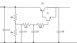
Your statement , "A gyrator has the property that if you connect a capacitor at its output port, you will see an inductance at its input port, or if you connect an inductor at its output port, you will see capacitance at its input port." has me wondering what is what in the Gyrator section of Rod's schematic. I also wonder how to figure out the impedance seen by the filament. Looking back into the emitter on the NPN , isn't it fairly low?
Also , until planet10's mention of it , I'd missed your post on the Tellegen .pdf . I very much appreciate your offer but I am not yet able to translate complex theoretical math into design and component choices so if his paper is more than 50% equations it's not likely I'd be able to make good use of it.
Thanks again!
Hearinspace said:
...has me wondering what is what in the Gyrator section of Rod's schematic. I also wonder how to figure out the impedance seen by the filament. Looking back into the emitter on the NPN , isn't it fairly low?
Thanks again!
In post #13 of this thread, Poynton says that the part of the circuit labeled gyrator is really a capacitance multiplier. I agree, and I would think the impedance looking into the emitter of T1 (also the collector of Q1) is very low. However, Coleman says that he considered using a current source at both filament terminals, but that the configuration he shows gave better performance. I'm not sure why that would be, but I can't dispute his findings.
But, the T1/Q1 combo isn't a gyrator as I understand the term. A gyrator should have a high impedance at its output terminal, increasing with increasing frequency, and this circuit appears to have a low impedance. I'll see about some analysis when the ice storm we're about to have here in the PNW is over.
- Status
- This old topic is closed. If you want to reopen this topic, contact a moderator using the "Report Post" button.
- Home
- General Interest
- Everything Else
- Looking for Transistor based Gyrator info. Any "Wireless World" collectors out there?