Hi, all.
Below is something I've written and plan to put up on the DIYAudio Wiki along with my other contributions. I am running this through the community since it's not something so easily standardized such as the basics.
Please correct me if I make a mistake. I know there are engineers out there with far more experience than me, so if you do not want a hideously misleading article on our WIKI then help me make this article worthwhile! If there are no comments for a few days, I will assume no one minds me adding this to the wiki.
I used Doug's circuit as an example because it was the only one I could find.
-------------------------------------
= Modulating a CCS =
This article will discuss, for those who are interested, the implications of modulating the output of a CCS.
Normally a CCS is used when a precise (or at least predictable and controllable) current is needed to either act as a reference or isolate different signals.
CCSs are designed to provide a steady, controlled, and predictable amount of current. However, there is an aspect of many discrete CCS designs that enables and beckons for further development.
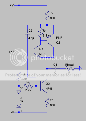
Doug Self on his website mentions the advantages of using a modulated CCS to improve the load-driving capability of the CFP common-emitter without increasing distortion.
http://www.dself.dsl.pipex.com/ampins/discrete/cfp.htm
This is only one of the possible applications. However, my aim is to expand upon the technical aspects of the signal-modulated CCS, not its application. Development into practical applications will be left to the reader, the DIYer, for which this article was written.
The method Doug uses modulates the base voltage of the transistor with the the help of the 2K2 resistor. If the CCS was to be made more amp-like a capacitor could be put in parallel with the 100R resistor to decrease AC impedance through the base. This would increase OLG and thus increase the effect and extent of feedback (although considering the circuit originally delivers below .0008% THD, it is unlikely that it needs it!).
At any rate there are ways to modulate a CCS without impeding its function. Remember, we still want it to be a CCS afterwards. My aim in this article is to present methods by which to attain modulation without adding components which may degrade the CCS's function.
Note: An extra resistor or two shouldn't be disastrous, however this is an in-depth analysis so I am willing to swat gnats with a buick.")
The following will not improve Doug's circuit because the following modifications will make it incompatible. So the above should only be thought of as an example.
Firstly, I would delete the 2.2k resistor and put the input point at Q1s emitter. This makes one less component, but with the same effect. This causes the output to be an inverted version of the input, which makes it unusable for Doug's circuit, however.
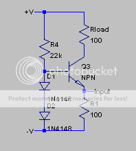
Now say we insert a positive signal of 1mV at the input. This will raise the voltage across the resistor by .1V, causing it to conduct more current, causing the output of the CCS to rise, right? No! The voltage across the resistor doesn't change. You see, the CCS tries to keep the the voltage (and therefore current) across the resistor steady, and so this current also flows through the collector of the transistor. So in effect, this particular CCS uses no feedback from the output!. It does not monitor the output current, only the voltage across the resistor.
So when we insert a signal we are really only changing Vbe enough to keep 0.6V across the resistor. And when Vbe changes, collector current changes also, and you have output modulation. To all intents and purposes, what is really happening is that whenever you insert a signal at the input, you are changing the resistance of R1!
Now say the impedance of the two diodes becomes a problem, and we want better AC response. We just bypass the diodes with a capacitor. This has the added advantage of filtering noise generated by the diodes.
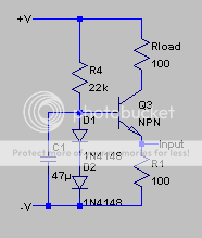
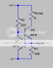
Personally, I like the following circuit over the above examples, since the input impedance (at DC) is the lowest.
-------------------------------------
- keantoken
Below is something I've written and plan to put up on the DIYAudio Wiki along with my other contributions. I am running this through the community since it's not something so easily standardized such as the basics.
Please correct me if I make a mistake. I know there are engineers out there with far more experience than me, so if you do not want a hideously misleading article on our WIKI then help me make this article worthwhile! If there are no comments for a few days, I will assume no one minds me adding this to the wiki.
I used Doug's circuit as an example because it was the only one I could find.
-------------------------------------
= Modulating a CCS =
This article will discuss, for those who are interested, the implications of modulating the output of a CCS.
Normally a CCS is used when a precise (or at least predictable and controllable) current is needed to either act as a reference or isolate different signals.
CCSs are designed to provide a steady, controlled, and predictable amount of current. However, there is an aspect of many discrete CCS designs that enables and beckons for further development.
Doug Self on his website mentions the advantages of using a modulated CCS to improve the load-driving capability of the CFP common-emitter without increasing distortion.
http://www.dself.dsl.pipex.com/ampins/discrete/cfp.htm
This is only one of the possible applications. However, my aim is to expand upon the technical aspects of the signal-modulated CCS, not its application. Development into practical applications will be left to the reader, the DIYer, for which this article was written.
The method Doug uses modulates the base voltage of the transistor with the the help of the 2K2 resistor. If the CCS was to be made more amp-like a capacitor could be put in parallel with the 100R resistor to decrease AC impedance through the base. This would increase OLG and thus increase the effect and extent of feedback (although considering the circuit originally delivers below .0008% THD, it is unlikely that it needs it!).
At any rate there are ways to modulate a CCS without impeding its function. Remember, we still want it to be a CCS afterwards. My aim in this article is to present methods by which to attain modulation without adding components which may degrade the CCS's function.
Note: An extra resistor or two shouldn't be disastrous, however this is an in-depth analysis so I am willing to swat gnats with a buick.
The following will not improve Doug's circuit because the following modifications will make it incompatible. So the above should only be thought of as an example.
Firstly, I would delete the 2.2k resistor and put the input point at Q1s emitter. This makes one less component, but with the same effect. This causes the output to be an inverted version of the input, which makes it unusable for Doug's circuit, however.
Now say we insert a positive signal of 1mV at the input. This will raise the voltage across the resistor by .1V, causing it to conduct more current, causing the output of the CCS to rise, right? No! The voltage across the resistor doesn't change. You see, the CCS tries to keep the the voltage (and therefore current) across the resistor steady, and so this current also flows through the collector of the transistor. So in effect, this particular CCS uses no feedback from the output!. It does not monitor the output current, only the voltage across the resistor.
So when we insert a signal we are really only changing Vbe enough to keep 0.6V across the resistor. And when Vbe changes, collector current changes also, and you have output modulation. To all intents and purposes, what is really happening is that whenever you insert a signal at the input, you are changing the resistance of R1!
Now say the impedance of the two diodes becomes a problem, and we want better AC response. We just bypass the diodes with a capacitor. This has the added advantage of filtering noise generated by the diodes.
Personally, I like the following circuit over the above examples, since the input impedance (at DC) is the lowest.
-------------------------------------
- keantoken
Keantoken,
I have some difficulty to understand this. For example, if you say to input +1mV at the input, then the input voltage at the top of the resistor rises by 1mV. The bottom of that resistor is at -12V, so whatever you reasoning, it is clear that the voltage across the resistor rises. You cannot have +1mV across the resistor and at the same time no voltage change.
Jan Didden
I have some difficulty to understand this. For example, if you say to input +1mV at the input, then the input voltage at the top of the resistor rises by 1mV. The bottom of that resistor is at -12V, so whatever you reasoning, it is clear that the voltage across the resistor rises. You cannot have +1mV across the resistor and at the same time no voltage change.
Okay, I see. In my example there are two voltage sources across the resistor: one is the CCS, the other is the input signal. The voltage across the resistor doesn't change; it is steady at 0.6V. When an input signal of 100mV is inserted, the transistor will turn off so that it's just supplying 500mV to compensate. So there will still be 0.6V across the resistor, just less coming from the transistor and the remaining from the input. Likewise, if we try to steal 100mV, the transistor will give 700mV to compensate, and the current from the output will rise.
A more useful and practical analogy is that any extra current at the input will be taken baway from the input; any rise in current at the input will cause an equal fall in current at the output.
Thank you for pointing that out, I will edit the article now.
EDIT: Oops, can't edit my first post. At any rate, here is what I changed. I also defined TLA's, except for the CFP because all you have to do is click the link and you'll find out what it is.
Now say we insert a positive signal of 100mV at the input. This will raise the voltage across the resistor by 100mV, causing it to conduct more current, causing the output of the CCS to rise, right? No! The voltage across the resistor doesn't change. The CCS will 'turn off' just enough to compensate for the .1V that it no longer needs to supply. If we instead try to take away 100mV, than the transistor will compensate again by supplying an extra 100mV. So whatever value we input, the transistor compensates by the same amount to keep the voltage at 0.6V. This affects current in the same way. If we take away 100uA, the transistor will increase its current by 100uA to compensate, and the output will rise by this same amount.
- keantoken
Keantoken,
It should help if you number the resistors like R1, R2 and specify whih circuit you are referring to. Sometimes you talk about 'the 100 ohms' and I see two of those in the original drawing. Then you talk about 'the resistor'. Which resistor do you actually mean ?
Jan Didden
It should help if you number the resistors like R1, R2 and specify whih circuit you are referring to. Sometimes you talk about 'the 100 ohms' and I see two of those in the original drawing. Then you talk about 'the resistor'. Which resistor do you actually mean ?
Jan Didden
- Status
- This old topic is closed. If you want to reopen this topic, contact a moderator using the "Report Post" button.