Clc Psu
Hi Karl,
I removed the earth from the PSU last night. Then I took a stab at it with the probe connected between the rectifier and the first set of capacitor banks. It was difficult to make out the exact value. I just adjust the Volt/Div and Sec/Div until I saw a couple of /\/\/ not sine wave the upward curve is steep but the downward curve is not steep at all. (Will take picture tonight it was 12:45pm late and felt very tired). But when I move the probe to after the inductor coil and the second bank of capacitors it was even more difficult to get the display properly no matter how I adjust the dials. May be I need to use the 10X probe? I am still waiting for it in the post.
I may try different 2N3055 one at a time to see if it get any better first before trying different emitter resistors.
Best Regards,
O.K. bit more time now. One of those days ")
Connect your 'scope ground lead on the probe to the PSU zero volt line, that's the negative end of C6 and the positive end C7 on your circuit or just to the negative speaker socket if you prefer. If you set your scope to say 5 volts/ div and AC coupled so that the trace stays central and is not offset by the rail voltage you should be able to read the ripple. Set the timebase to around 5 milliseconds per div so you can get a few complete cycles on screen and make sure the triggering is on internal and set for Channel one if that is what you are using. By adjusting the trig controls you should get a stable display. The ripple will be in the range of, what, 2 to 3 volts peak to peak, says he taking a wild guess. Depends how much current the amp is drawing.
Connect your 'scope ground lead on the probe to the PSU zero volt line, that's the negative end of C6 and the positive end C7 on your circuit or just to the negative speaker socket if you prefer. If you set your scope to say 5 volts/ div and AC coupled so that the trace stays central and is not offset by the rail voltage you should be able to read the ripple. Set the timebase to around 5 milliseconds per div so you can get a few complete cycles on screen and make sure the triggering is on internal and set for Channel one if that is what you are using. By adjusting the trig controls you should get a stable display. The ripple will be in the range of, what, 2 to 3 volts peak to peak, says he taking a wild guess. Depends how much current the amp is drawing.
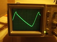
The AC measured before the smoothing caps and right after the rectifier.
Volts/Div is set at 0.1
Sec/Div is set at 1 ms
The cycle takes 8.2 division
8.2 X 1ms= 8.2ms
Convert ms to second 8.2ms / 1000 = 0.0082
1 / Time in second = Frequency
1 / 0.0082 = 122 Hz
Volts/Div is set at 0.1
Sec/Div is set at 1 ms
The cycle takes 8.2 division
8.2 X 1ms= 8.2ms
Convert ms to second 8.2ms / 1000 = 0.0082
1 / Time in second = Frequency
1 / 0.0082 = 122 Hz
Attachments
Hi Chris,
That looks O.K. You have worked the frequency out to 122 Hz. I take it in your part of the world it's 60Hz mains. So what you are seeing is the effect of the bridge (full wave rectifier) topping up the caps each half cycle-- thats why you are seeing 122 (It will be 120Hz, but measuring that accurately on a 'scope is not easy).
Your first pic shows the voltage on the cap rising as the bridge starts to conduct, the voltage keeps rising untill the mains is at its "peak" and then the caps maintain the rail voltage as the mains falls away. The falling part of the waveform is the cap discharging as the amp draws current, when the next half cycle comes along the process repeats. The bridge only conducts when the voltage on the rising part of the incoming half cycle exceeds the DC voltage on the cap ( +0.7 volts diode drop ). If you vary the quiescent current of your amp you will see the ripple voltage vary. This ripple is sat "on top" of the D.C. voltage of the rail. So at 0.1 V/Div you only have 0.6 volts peak to peak-- that sounds very good to me.
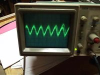
Second shot, if you are on 2mv/div ( 2 MILLIVOLTS ), that really is a half of a quarter of nothing .
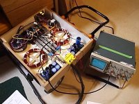
Must be those coils , they look like something out of a particle acccelerator !
I am sure you are right but can you just confirm, pic two looks as though there is a low frequency component lurking there. Try and keep the timebase the same as in shot one and just alter the volts/div setting-- and make sure any variable gain pots are in "cal"
Try measuring directly across the speaker outputs for interest, with the inputs to the amp shorted. If the 'scope trace seems to "thicken" but you can't make anything out turn the timebase to much higher speeds, this will show if there is any high frequency oscillation of any sort.
That looks O.K. You have worked the frequency out to 122 Hz. I take it in your part of the world it's 60Hz mains. So what you are seeing is the effect of the bridge (full wave rectifier) topping up the caps each half cycle-- thats why you are seeing 122 (It will be 120Hz, but measuring that accurately on a 'scope is not easy).
Your first pic shows the voltage on the cap rising as the bridge starts to conduct, the voltage keeps rising untill the mains is at its "peak" and then the caps maintain the rail voltage as the mains falls away. The falling part of the waveform is the cap discharging as the amp draws current, when the next half cycle comes along the process repeats. The bridge only conducts when the voltage on the rising part of the incoming half cycle exceeds the DC voltage on the cap ( +0.7 volts diode drop ). If you vary the quiescent current of your amp you will see the ripple voltage vary. This ripple is sat "on top" of the D.C. voltage of the rail. So at 0.1 V/Div you only have 0.6 volts peak to peak-- that sounds very good to me.
Second shot, if you are on 2mv/div ( 2 MILLIVOLTS
), that really is a half of a quarter of nothing .Must be those coils
, they look like something out of a particle acccelerator ! I am sure you are right but can you just confirm, pic two looks as though there is a low frequency component lurking there. Try and keep the timebase the same as in shot one and just alter the volts/div setting-- and make sure any variable gain pots are in "cal"
Try measuring directly across the speaker outputs for interest, with the inputs to the amp shorted. If the 'scope trace seems to "thicken" but you can't make anything out turn the timebase to much higher speeds, this will show if there is any high frequency oscillation of any sort.
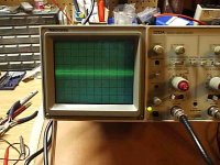
At the speaker outputs
OK,
Volts/Div is set at 2mV
Sec/Div is set at 1ms
Input is short---the whole band(line/trace) is like the picture below very steady
Input NOT short--- the whole band wave a little bit and not steady
EDIT: But this is the same even after the power is turn off. The same band(trace) appeared anyway
EDIT#2: I connected/shorted the probes together and get the same trace.
Attachments
Hi,
Nothing strange going on--- you are discovering the mysteries and limitations of doing simple but sensitive measurements with simple test gear and wiring arrangements.
The 'scope trace is ( looks like from here-- let's put it that way ) just white noise. You say with the inputs to the amp NOT shorted you get a on the trace. That's just the noise being modulated by the stray 60 Hz pickup.
Just to be absolutely sure, with it as in your picture turn the 'scope gain up as high as it goes, and expand the timebase to much higher speeds-- is it still just noise or is there any kind of "sinewave" lurking there. Almost certainly not, it's just a check to make sure it really is just noise.
Now your last comment-- with the scope set to 2mv/Div and timebase back at 2m/s Div and the scope leads connected together but NOT touching the amp is the trace still "thick" with noise. It should not be. If it is disconnect the probe from the front and see it it goes back to normal.
Did that info arrive by the way ?
Nothing strange going on--- you are discovering the mysteries and limitations of doing simple but sensitive measurements with simple test gear and wiring arrangements.
The 'scope trace is ( looks like from here-- let's put it that way ) just white noise. You say with the inputs to the amp NOT shorted you get a
on the trace. That's just the noise being modulated by the stray 60 Hz pickup.Just to be absolutely sure, with it as in your picture turn the 'scope gain up as high as it goes, and expand the timebase to much higher speeds-- is it still just noise or is there any kind of "sinewave" lurking there. Almost certainly not, it's just a check to make sure it really is just noise.
Now your last comment-- with the scope set to 2mv/Div and timebase back at 2m/s Div and the scope leads connected together but NOT touching the amp is the trace still "thick" with noise. It should not be. If it is disconnect the probe from the front and see it it goes back to normal.
Did that info arrive by the way ?
Mooly said:Did that info arrive by the way ?
Yes it did thank you very much.
I will try what you suggest later this weekend.
After fixing the fish tank water pump broke down problem the last few days back in business.
The 10X probe arrived and I used it set at 10X across the speaker output with input shorted. Can not measure anything wrong with all kinds of settings.
The only thing I noticed is that since it is still connected to the mains via VariAC
When the DC rail at the amp board is 25V
Q2a/R15 is at 56mV
Q2 /R13 is at 86mV
Q1a/R16 is at 88mV
Q1 /R14 is at 55mV
When the DC rail at the amp board is 29V
Q2a/R15 is at 14mV
Q2 /R13 is at 107mV
Q1a/R16 is at 81mV
Q1 /R14 is at 41mV
When I connect to the mains directly the DC rails are at 30.5V and the load is really tilt to one side the R13 and R14 is taking the 90 % of the load
Could that be because of the driver transistors causing this effect with higher DC rail supply? Or it is still due to the different charactericstics of the 2N3055?
Any other way to measure and see if the amp is stable? I am trying to find a pre-amp to connect to the CD player or can I just use a 25ohm / 3 watts wirewound potentiometer as volume control instead?
Regards,
Hello Chris,
Easy one first-- 25 ohm pot is way to low to use as a volume control. 10K to 100K is fine, you need a dual gang pot preferably with a logarithmic track but a linear is OK as well. Try to get 10 or 22 k if you can. Do you know how to wire it up ?
These unbalanced currents. You have to understand the way a transistor operates to visualise whats going on. I will just take the lower pair as an example Q1 and Q1 A. Firstly the characteristics of each device can vary wildly and still be "in spec"
The current gain or hfe may be as low as 15 for one and as high as 50 for another. The base emmiter junction will not pass current until a voltage of around 0.6 to 0.7volt is across it at which point the device will begin to conduct and current will flow from collector to emmiter. How much current depends largely on the gain of the device. Temperature also plays a big part, even if you had matched them, if one were hotter than the other the "gain" and other characteristics vary.
The circuit designer should ensure that these variations do not upset the performance of the circuit and that the circuit will work with all devices, whether they are at the top or bottom of the specification.
So back to your circuit, the volt drop across R9 biases the transistors into conduction. If Q1 and Q1A were identical and R14 and 16 are equal the current MUST be shared equally. In practice this will never occur, so what can be done ? This is where R14 and 16 come in. Imagine Q1 begins to conduct a bit more-- it gets hotter-- this increase the hfe-- so it conducts more still. This higher current will increase the volt drop across R14, so the effective base and emmiter voltage is now slightly less. This reduction will (but in your case it's not enough) cause the current to reduce and hopefully share more equally.
This is why I suggested increasing the value of all the emmiter resistors to say 0.33 or 0.47 ohms. This will tend to force the outputs to equalise the currents more equally as the variations in current will cause more of a change in that all important base emmiter voltage. If you can also match the transistors then that helps as well.
Remember the bjt or junction transistor is NOT a "voltage" driven device but rather a cuurent driven one. This is why a tiny change in base emmiter voltage can cause such a large change in the collector current.
If the amp were unstable you would see it on the scope as an unwanted continuos signal probably in the 600khz to 5 Mhz range.
Presets eh. Well, it's a new one on me. If you can get some 0.5ohms pots well why not. Actually though, that set me thinking, its not so strange an idea. Well a bit maybe. Problem is the current Chris, it's to much. Many years ago TV's had such things in them for convergence adjustment etc, but they were big arkward things. No try increasing them first 0.33 or 0.47 and then perhaps you could ADD a parallel resistor across them on a selected one off basis to trim them--- there you are, so it wasn't a strange idea after all.
Mooly said:Have you got any low eg 0.47 0.33 0.22 etc 3 or 5 watt resistors spare. The transistor with the lowest voltage (current flow) of each pair is the one to trim by adding a resistor across it's emmiter resistor.
No I do not have them at hand. I have to go and buy them. Please let me know what values trimmer I do need as well.
Shopping here in Canada is not as easy so I try to make the trip worth it. I will have to drive 40km each way and hope they are not out of stock
Regards,
Spot on Awasson .
I still think it best to increase all four to at least 0.33 ohms first. You will never get it 100%, certainly not if the outputs are not all thermally in contact with one another but I would guess that if you can get it within 25% or so imbalance, thats not so bad.
If you are going shopping especially for these I would suggest you get 4 each of 0.47 and 0.33 and 0.22. Don't forget the volume pot 10 or 22K log dual gang.
.I still think it best to increase all four to at least 0.33 ohms first. You will never get it 100%, certainly not if the outputs are not all thermally in contact with one another but I would guess that if you can get it within 25% or so imbalance, thats not so bad.
If you are going shopping especially for these I would suggest you get 4 each of 0.47 and 0.33 and 0.22. Don't forget the volume pot 10 or 22K log dual gang.
- Status
- This old topic is closed. If you want to reopen this topic, contact a moderator using the "Report Post" button.
- Home
- General Interest
- Everything Else
- How to measure JLH Class A with a Scope