"Directional" Inverted LM3866T
Split from "just another Gainclone"
Dear fellows
It is not important if an other set of inverted chip power op amp has been built. OK. But i have to write to this thread again, this time for to thank all the contributors, as well as to admit in public that i have taken a lesson.
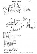
What i have built is seen on the attachment. LM3886T inverted. 11K to In-, 110k feedback (gain x10), +/- 37V DC unregulated. Initial operation with regulated bench PSU showed oscilation above 1W ouput if no bypass capacitors were used on the supply pins of the IC. So 100uF// 100nF were soldered directly at the +/- pins. DC offset with V+ grounded was ~ 150mV, but this varied enough, depending on the load seen by the input. I settled for 7K5//100nF from In+ to ground for 15mV DC offset at the output (+/- 5mV depending on the input load). I housed the amps on a small enclosure together with the PSU. The usual hum problems were dealth succesfully by carefull return path cabling (see attachment). 10mV/100Hz spikes at the output, not heard thru the speakers. Very stable operation, superb HF square wave output, burned in for a night, next day listening test. Jaw falling bass, but treble were like hidden behind a curtain. Quite the opposite from what i was expecting. More burning in with the dummy load, and i started doing my visit to this site. Somewhere, i fall on the issue of "component sound", then on "cable directivity" and finally on "resistors directivity". I didn't have enough trangualizing pills, so i switched off the PC. Next day some more listening test. Not much of a change. The dillema was raised. Either i will rebuild them as non-inverting, or i will turn to the TDA7294, both tested in the past with better results. Being quite lazy to do any of them, i tried something really easy, something that i didn't believe in. I tested the theory of the "resistors directivity". Each of the three resistors of the circuit was replaced with an antiparallel combination (2// resistors, but with their color coding on opposite direction). The result? I turned to listen to a totally different amplifier. What a clarity, what a detail! Now i had to swallow all the remaining pills. Me the subjectivist, me the orthologist to be broven wrong by three resistors and their idiosyncratic behaviour. This WAS a lesson for me, and i think i have to share it with you. It is not a joke.
Now this small amplifier has replaced my much beloved tube PP/class A/no global feedback. It is better indeed, very open, more clean, more detailed, faster, equally balanced, only it doesn't warm up my room.
It is driven equally well from my 1K CD or my <100R preamp. It's sound does change though with different interconnects.
Regards
Geor
Split from "just another Gainclone"
Dear fellows
It is not important if an other set of inverted chip power op amp has been built. OK. But i have to write to this thread again, this time for to thank all the contributors, as well as to admit in public that i have taken a lesson.
What i have built is seen on the attachment. LM3886T inverted. 11K to In-, 110k feedback (gain x10), +/- 37V DC unregulated. Initial operation with regulated bench PSU showed oscilation above 1W ouput if no bypass capacitors were used on the supply pins of the IC. So 100uF// 100nF were soldered directly at the +/- pins. DC offset with V+ grounded was ~ 150mV, but this varied enough, depending on the load seen by the input. I settled for 7K5//100nF from In+ to ground for 15mV DC offset at the output (+/- 5mV depending on the input load). I housed the amps on a small enclosure together with the PSU. The usual hum problems were dealth succesfully by carefull return path cabling (see attachment). 10mV/100Hz spikes at the output, not heard thru the speakers. Very stable operation, superb HF square wave output, burned in for a night, next day listening test. Jaw falling bass, but treble were like hidden behind a curtain. Quite the opposite from what i was expecting. More burning in with the dummy load, and i started doing my visit to this site. Somewhere, i fall on the issue of "component sound", then on "cable directivity" and finally on "resistors directivity". I didn't have enough trangualizing pills, so i switched off the PC. Next day some more listening test. Not much of a change. The dillema was raised. Either i will rebuild them as non-inverting, or i will turn to the TDA7294, both tested in the past with better results. Being quite lazy to do any of them, i tried something really easy, something that i didn't believe in. I tested the theory of the "resistors directivity". Each of the three resistors of the circuit was replaced with an antiparallel combination (2// resistors, but with their color coding on opposite direction). The result? I turned to listen to a totally different amplifier. What a clarity, what a detail! Now i had to swallow all the remaining pills. Me the subjectivist, me the orthologist to be broven wrong by three resistors and their idiosyncratic behaviour. This WAS a lesson for me, and i think i have to share it with you. It is not a joke.
Now this small amplifier has replaced my much beloved tube PP/class A/no global feedback. It is better indeed, very open, more clean, more detailed, faster, equally balanced, only it doesn't warm up my room.
It is driven equally well from my 1K CD or my <100R preamp. It's sound does change though with different interconnects.
Regards
Geor
Ah, but was the direction the issue or was it a thermal effect due to having two resistors in parallel and thus able to dissipate twice the power for the same temperature rise? Or was it that you started with a cold solder joint, and when you put in the new resistors you made a good joint? Or is the physical position of the new resistor pair different from the original so the stray capacitive coupling has changed? Or was there some defect in the original resistor which was eliminated when you put in two new resistors?
Some have expressed an opinion that resistors are "directional". My opinion is that I'd like to get some of whatever they've been smoking...
MR
Some have expressed an opinion that resistors are "directional". My opinion is that I'd like to get some of whatever they've been smoking...
MR
MRehorst said:Some have expressed an opinion that resistors are "directional". My opinion is that I'd like to get some of whatever they've been smoking...
Just don't be a bogart.
")
se
Originally posted by MRehorst
"Ah, but was the direction the issue or was it a thermal effect due to having two resistors in parallel and thus able to dissipate twice the power for the same temperature rise? Or was it that you started with a cold solder joint, and when you put in the new resistors you made a good joint? Or is the physical position of the new resistor pair different from the original so the stray capacitive coupling has changed? Or was there some defect in the original resistor which was eliminated when you put in two new resistors? "
===========================================
Dear MRehorst
You are right in doubting the directivity effect, because it is a bit of funcy. (me also, didn't like it. I have to go through some of my other equipment, do there some resistor changes, see of any differences and report back). I myself have thought of all of your concerns, but nothing seems to be the issue. The resistors i had initially installed were R6, R7: carbon 1/2W. Replaced each with 2 carbon 1/4W. R5:metal film 1/2W (0.6W). Replaced with 2 metal film 1/4W. Parallel combination was placed at exactly the same location as single resistors. Cold solder joint and resistor defect was not either. The first trial was with a gain of X20. Then i went for a gain of X10 (resistors changed). The same sound character in both cases, on both channels. Then i did the paralleling and heard the difference, which is obvious at all level settings, amp cold or warmed-up. My room is small (4mx4mx3m) and the amp does not have to play higher than approx a mean of 3-4 WRMS (Speakers 8R, 89db/1m/1W). When i did some auditing to a friend's house (room 10mx6mx3m), the amp behaved very well at normal listening levels. At high levels it started to distort (heatsink not more than 45 d. Celcius), something i was expecting, as his speakers are 4R nominal, 89db. The LM3886 data sheets don't make any firm statement about, except that the power dissipation increases, but the supplied graphs do imply that for 4R load, power supply has to be less than +/_ 30V DC. My PSU is +/_ 37V no drive, +/_ 30V full continuous drive.
By the way, i did some measurements which might be of interest to some.
The 100Hz ripple up and downstream of R1 are 2 to 1 (200mVpp/100mVpp no signal, 2500mVpp/1200mVpp at 18WRMS out).
The modulation of Vsupply by audio signal at 18 WRMS out (both channels driven) is as follows:
Freq. (Hz) // Modulation (Vpp)
10 // 10
20 // 9
30 // 7
40 // 6
50 // 5
100 // 2.8
250 // 1.6
500 // 0.8
1000 // 0.4
2500 // 0.15
5000 // 0.1
10000 // 0.1
. .
. .
The modulation of the Vsupply of the undriven LH amp by the 18WRMS driven RH amp., although they share the same x-former was les than 20mVpp at all frequencies. Not bad at all.
I would be helpfull if somebody was doing some "resistors directivity" verification test with his inverted gainclone and report the results here. I would be more than happy if my findings were proven wrong. Then, things would seem to be normal again!
Regards
George
Hi gpapag,
Don't be deterred by any of the usual comments which always come out of the woodwork if you post anything like this. It is all too easy to sit in a chair and ridicule what others have discovered and it is merely a cover for their own lazyness in many cases.
If I may offer a suggestion based on my own long-term listening experiences, I would suggest that you should try to 'reverse' the experiment, and ideally do this change back and forth, several times.
Doing this will eliminate any other unwanted variables of which you may not be aware, and provided that the results are always consistent each way, then you will know *without any doubt* that it is the reversal (or whatever) of the resistors which is responsible for any changes you hear.
I have been 'listening' to components for about 30 years now, and I don't mind admitting that, in the early days, I made many mistakes in reaching some of my initial conclusions, due to inexperience.
One of these times was after making some change, and I was initially pleased to hear an immediate improvement, but later on after subsequently reversing the change (because I wished to try the 'new' cap in another circuit to see if its apparent beneficial effect was universal) the improvement remained!
Therefore it couldn't have been the change of cap which was responsible for any sonic difference, but I knew that the change was real and not illusory.
It was therefore clear to me (probably as I had not made any other changes for some months) that most likely the 'cleaning' effect caused by disconnecting and reconnecting the cables (which had remained undisturbed for so long) was actually responsible for the 'improvement' which I heard.
All connections (whether gold plated or whatever) will tend to deteriorate over time due to tarnishing of connectors etc., and simply cleaning them (either accidentally, or deliberately!) will generally effect some improvement to the overall sound quality.
Similarly, a previously undetected poor (dry) soldered joint can be remedied during the 'substitution' process, but if you do as I suggest and reverse the change a couple of times, it overcomes any of these possibilities.
Since becoming aware of the likelihood of being lead astray by any of these false effects, I will always now do the 'reversal' trials, even though it is an added aggravation and takes up more time, as this is the only way of being absolutely certain over the reasons for any perceived differences in the sound.
You do need to eliminate any extraneous influences, and if an experiment can be done and reversed repeatedly, and consistently, then you are guaranteed that this is the cause of whatever differences you hear.
I would be very interested to hear some more about your trials, as, most unusually, directionality in resistors, is one of the very few tweaks which I haven't yet tried for myself.
Regards,
Dear Bobken
Thanks for the encourangement. I was very sceptical posting my findings. I too hate black art, magic or whatever is not explainable (let alone if it costs an arm and a leg). The reason that i did not any reversing, is that this amps are hard wired and all the components are wired on the pins of the ICs. So it is not easy to change a component withought damaging something. But I HAVE to do extensive testing as you suggest, and the only way to do it is to build in the open 2 LM1875 which have only 5 pins. As long as i have some new evidence, i will report back.
Regards
George
Peter Daniel said:Here's the link: http://www.diyaudio.com/forums/showthread.php?s=&postid=123835#post123835 and the pic of a test setup.
I can see a number of problems this set-up that I think would make it a very unreliable way to check resistor "directivity" or any other aspect of component "sound".
This unshielded arrangement is going to be prone to all sorts of radiation and noise pickup. There's a good chance that such noise will mask any effect of component "directionality", if any exists.
Then there's the contact method. Just relying on the spring force the leads provide is an extremely poor way to make contact with the part. Every time you move it (or some sound in the room vibrates it) the characteristics of the contacts will change. The plating on the component leads and the plating on the connectors may be different materials forming point contact diodes. Dirt or crud on either the leads or the connectors will interfere with the connection.
I think a better test would be to build two identical amplifiers with all the components matched and installed with the same "polarity". Build it in a properly shielded enclosure and use a quiet power supply. Feed the same signal into both amps, then observe the difference between the outputs. This will be the baseline. Next reverse the one component in question, and observe the difference between the outputs. I would use a simple amplifier such as a very low noise, low distortion, wide bandwidth op-amp, one with multiple amps on a single chip to ensure that they are matched. The outputs of those amps would drive a similarly low noise, wide band, low distortion instrumentation amplifier. Observation would be done in both frequency (spectrum analyzer, noise analyzer, etc.) and time domain (oscilloscope, freq selective voltmeter, etc.). Several different test signals, steady and dynamic, could be devised and applied to the circuit to check specific aspects of the behaviour.
Such a test set up would require a lot of time, money and effort. Not many people have the access to such equipment. Even fewer of those who do would be interested in performing such a test.
Oh well...
MR
MRehorst said:What you think is a difference between resistors may just be a difference between poor contact with the connectors. Radiation is not steady state, so when performing different tests at different times, one may be subject to radiation that the other is not.
If this differences are consistant in subsequent testing for certain brands of resistors, I'm ruling out poor contacts factor. I made the tests in a period of 20 minutes, so I ruled out changing conditions as well. Why don't you try it yourself and agree with me?
I did quite a few tests of this type and can assure you that quality of the contact is not a problem here. Controling vibrations ibrations is a totaly different issue.
hifiZen said:C'mon Pete! I know you can do a more scientific test than this! Let's see those construction skills shine!
Well, as long as he's doing the testing (i.e. listening) sighted, it's really not much of a scientific test to begin with, construction skills notwithstanding.
se
Steve Eddy said:
And the process isn't really different. When you were sitting listening to various resistors connected in both directions using your impromptu test rig, you were listening just as intently and analytically as you would be during a blind test. The ONLY difference is that under blind conditions, you wouldn't know beforehand which resistor you were listening to or which direction it was in.
And if you were able to discern a difference under sighted conditions, then there's no reason you wouldn't be able to discern those same differences under blind conditions if the difference were truly audible.
Whatever it was (true or not), I am glad that I could decide for myself, which way to put those resistors in a circuit and that the last amount of doubt is gone. Now, both my conscious and subconscious mind is happy.
Steve,
Do you find any subjective differing directional results ?.
If you do, then there must be a physical reason, yeah ?.
I do use my DPDT transformer arrangement so that I can easily select AP at my speakers, but that was not my question.
BTW - are you saying that you cannot hear AP ?.
Go and read the thread that Frank refers to above and you will be clearer on what we mean.
How exactly can your mind be sub-concious ?.
In my younger years I read the brocures, and believed the spiels to be true.
When the salesman plugged in say, 'Monster cables', and said "Hear that better bass ?" etc, upon that power of suggestion, I did.
On subsequent learning, and far greater experience, I now do not pay the merest heed to such suggestion.
In my formative years, I did indeed perform experiments, and automatically considered them to be beneficial.
In later experimenting, I have learned that one can make very fine audible differences, but these are not always beneficial fine differences, especially with long term listening.
I am now well enough practised in this, that I find that I have a long term listenability/enjoyability handle on a new sound in about 5 seconds, and that these impressions prove to be accurate longer term.
Within my experience, I fully expect that C37 and Tubolator do affect/effect system sound, however based on my experience, I am not sure that the effect is particularly significant, nor entirely likeable - this requires personal experience of these products, and that I do not have, and my soloution is quite different.
Eric.
Well, yeah this is what we are on about.Sure. But when I do stuff like that, I'm just looking to see if I have any particular subjective preference. Not to establish any sort of physical reality beyond my own subjective perceptions.
Do you find any subjective differing directional results ?.
If you do, then there must be a physical reason, yeah ?.
I meant changing polarity of input and output connections together in order conserve throughput polarity, but invert wire and transformer core polarity.Well, if there's anything to the audibility of absolute acoustic polarity (see Clark Johnsen's book, The Wood Effect), then making such a switch in polarity could result in audible effects which have nothing to do with the directionality of conductors. You're changing compression to rarefication and vice versa.
I do use my DPDT transformer arrangement so that I can easily select AP at my speakers, but that was not my question.
BTW - are you saying that you cannot hear AP ?.
These differences were not subtle.Great. However there have been some number of others who have made the same claims of "non-subtle audible differences" only to mysteriously have their ability to discern those "non-subtle" differences evaporate the moment the identity of the cable they're listening to is withheld from them.
Go and read the thread that Frank refers to above and you will be clearer on what we mean.
Double blind testing is typically worth less than a pinch of you know what, because of unfamiliarity with system variables - A/B testing blind or not is perfectly valid on a very familiar home system.Coming from someone who is wholly uncomfortable with the notion that they're a mere mortal human being, this comment is not suprising.
I am perfectly concious of what my ears communicate, and I am perfectly familiar with interpreting this information under all sorts of conditions.I realize that there are some number of people who believe they can wholly divorce their conscious mind from their subconscious mind. But so far, all we have are empty claims.
How exactly can your mind be sub-concious ?.
Fine fair enough point.Yet the converse is somehow not also true? If one cannot hear something which is actually audible simply because they believe it to not be possible, why cannot someone perceive a difference when no audible difference exist simply because they believe it is possible?
In my younger years I read the brocures, and believed the spiels to be true.
When the salesman plugged in say, 'Monster cables', and said "Hear that better bass ?" etc, upon that power of suggestion, I did.
On subsequent learning, and far greater experience, I now do not pay the merest heed to such suggestion.
In my formative years, I did indeed perform experiments, and automatically considered them to be beneficial.
In later experimenting, I have learned that one can make very fine audible differences, but these are not always beneficial fine differences, especially with long term listening.
I am now well enough practised in this, that I find that I have a long term listenability/enjoyability handle on a new sound in about 5 seconds, and that these impressions prove to be accurate longer term.
I thought that you were asserting that the claims of C37 and Tubolator cannot be true, or indeed possible ?.I'm not the one making the empty claims of fact here. Nor do I have any particular desire to attempt to establish any of my subjective perceptions as any sort of physical reality.
I do not swallow weird claims either, but I do studty the claims, reviews and information given, in order to sort the wheat from the chaff.Yet you expect others to unquestioningly swallow the baseless claims of "yaysayers." Hmmm...
And FYI, I'm not a "naysayer." I just don't swallow empty claims without question. It's called having an open mind but not one so open their brains slosh out onto the floor.
Within my experience, I fully expect that C37 and Tubolator do affect/effect system sound, however based on my experience, I am not sure that the effect is particularly significant, nor entirely likeable - this requires personal experience of these products, and that I do not have, and my soloution is quite different.
Eric.
Peter Daniel said:It may surprise some of you, but I'll always choose convenience over reliability.
This supposed to be only a temporary and easy introduction to resistors comparison tests. I'm not claiming that this is a best way to do it, but if someone is reluctant to try those tests because of complexity of a setup, this should show a simple way to do it. If you try my method and will find that there is something to the differences presented, by no means go for more elaborate testing and use solder joints and all the rest of "perfect sound forever" accessories. For me this was good enough.
My point was that your simple test method is NOT a way to do the test. It is like sticking the resistors in your ears to see what the "sound" difference is. When the contact is unreliable, and the device is unshielded, you don't know what you may or may not be hearing.
If you want to do such a simple test setup and use only ears to evaluate the result, then shield the thing (just put it in a grounded box), an connect the resistor or other part to be tested using some binding posts or nuts and bolts and use a torque wrench to tighten the nuts uniformly and repeatably.
Whether THAT is a valid test is still debatable, but at least it should lead to repeatable results with minimized "noise".
There is another issue to consider- do resistors sound the same when they have only ac signals across them? Does ac + dc cause different sound? Does dc polarity and level affect the sound?
If none of this matters, and the whole point of the exercise is to fool yourself into thinking that you have actually tested something and have some valid results then your test set up really is optimal.
MR
MRehorst said:Let me put it into terms that will be more clear to the parties involved: if I were to claim that using a stick of spagetti I can drill holes through aluminum faster than a drill bit, and stuck to that argument no matter what anyone said, I would be laughed off these forums. If I said you have to try it to know, again people would laugh.
Your example here, may seem funny to you, but it only shows how exaggerated your attitude is, towards the whole issue. Although your avatar shows an attempt to have an open mind, this is not a way to achieve it.
Peter Daniel said:Whatever it was (true or not), I am glad that I could decide for myself, which way to put those resistors in a circuit and that the last amount of doubt is gone. Now, both my conscious and subconscious mind is happy.
And that's fine with me. That's how I approach it as well. If I subjectively prefer something, I go with it, whether it's due to physics or psychology. Just that unlike mrfeedback, I don't automatically assume and subsequently claim that my subjective perceptions are the result of actual audible stimuli.
se
MRehorst said:
-- snip --
I am a professional engineer with 20+ years of experience designing ICs and test circuits for them. I have spent thousands of hours in test labs with real test equipment devising methods and measuring characteristics of components. Over the years, companies have invested millions dollars based on the results of my lab work.
I have pointed out OBVIOUS flaws in the test set up, yet people keep denying they are flaws. It is like I am saying an apple is an apple and people keep insisting that it is an orange. Even my five year old son is more reasonable than this.
If the test method is bad, the results are meaningless garbage. There is no rational way to argue against this.
-- snip --
MR
I will have to agree with Peter on his response. I think this is the problem. I see this problem almost every day with engineers and I am one myself. It is so easy to believe that for a test to have any value it needs to be 100 % controlled, measurable and undisputable in every way. Not so.
I also have 20 years of experience in testing and devicing test methods. I, however, have absolutely no problem with the set-up when the intention is a quick test for the claimed differences. Sure the set-up is not "scientific", flawless or even close to perfect but that does not mean that it is completely useless. I don't argue the fact that there are OBVIOUS flaws in the test set-up but any flaw does not automatically disqualify all results from a test. The concept of repeatability also helps in the value of the results in this case.
- Status
- Not open for further replies.
- Home
- General Interest
- Everything Else
- Resistor Directionality and testing