OK...
I have built an invertor... oops let's call it a 60 Hz class D amplifier. At any rate, it is fairly efficient... in fact my first pass at measuring efficiency yielded a result of about 101%.
Normally... the poo would proudly beat his chest... and mail an invoice. I have made the mistake in this case of informing my client that 101% efficiency is probably not real.
The problems are obvious... one new 6.5 digit HP meter is here. The rest of the meters are at the cal lab right now...
Now... while I appreciate the ideas of calorimeters and the that junk... reality has to apply here as well.
So... one of the ways to eliminate variables is to use a fixed load resistor and measure the output RMS to calc. power out... all good.
I have 100 meters each of 0.05mm & 0.125mm manganin wire on the way. These are about 0.35 and 2.19 ohms per meter irrespectively.
The plan:
I plan to immerse these in a bath of food grade mineral oil... 18 "meg" or better. The bath will consist of a 5 gallon bucket(?), a temp probe, and pond pump or something. I can perhaps concoct some inner bucket/weir to force a nice fluid-flow loop.
The goal of said flow loop is keep the oil/wire temperature homogenous.
So... after I build this thing (yes... with Kelvin connections) I will take IT to the cal lab and have the resistance of various branches measured over temperature... so that I can fit a function and characterize them... blah blah.
THE QUESTION(s):
1. How should I wind this thing to minimize/avoid inductance?
2. Any bright ideas on coil forms? Please no real-high dollar solutions... McMaster Carr ideas are fine... and something better than a wicker wastebsket is probably justified.
OH... BTW, THD + N is running at about 0.23%... so, we don't have a lot of harmmonic trash to resonate in strays... or throw off the RMS-ser in the Voltmeter.
The output of the inverter is 100 Watts 24 VAC 60 Hz. Power is not a huge concern... it should really only be limited by fluid flow, fluid volume, and the melting temp of the resistor vessel (pickle bucket?) Test durations are not long anyway... I have PLENTY of loads for duration testing etc... Trying to measure efficiency... for a published spec... to +/- 0.1% says we need +/- 0.02% on contributing readings... easy to SAY.
Food fights are welcome...
And cool it on the buy-3-more-meters-thing too. That puts 2 meters in an RMS * RMS thing... bad. I need a stable high power resistor for this project ongoing. After hearing about the 101% efficiency... the client is asking for more models and sizes.
$50,000 for a new BURWICKEE & LIMPCOCKE AC analyzer won't do either. The client pays either way... I would rather the 50K went to The Poo Foundation for Drunken Women with Low Self-Esteem.
")
I have built an invertor... oops let's call it a 60 Hz class D amplifier. At any rate, it is fairly efficient... in fact my first pass at measuring efficiency yielded a result of about 101%.
Normally... the poo would proudly beat his chest... and mail an invoice. I have made the mistake in this case of informing my client that 101% efficiency is probably not real.
The problems are obvious... one new 6.5 digit HP meter is here. The rest of the meters are at the cal lab right now...
Now... while I appreciate the ideas of calorimeters and the that junk... reality has to apply here as well.
So... one of the ways to eliminate variables is to use a fixed load resistor and measure the output RMS to calc. power out... all good.
I have 100 meters each of 0.05mm & 0.125mm manganin wire on the way. These are about 0.35 and 2.19 ohms per meter irrespectively.
The plan:
I plan to immerse these in a bath of food grade mineral oil... 18 "meg" or better. The bath will consist of a 5 gallon bucket(?), a temp probe, and pond pump or something. I can perhaps concoct some inner bucket/weir to force a nice fluid-flow loop.
The goal of said flow loop is keep the oil/wire temperature homogenous.
So... after I build this thing (yes... with Kelvin connections) I will take IT to the cal lab and have the resistance of various branches measured over temperature... so that I can fit a function and characterize them... blah blah.
THE QUESTION(s):
1. How should I wind this thing to minimize/avoid inductance?
2. Any bright ideas on coil forms? Please no real-high dollar solutions... McMaster Carr ideas are fine... and something better than a wicker wastebsket is probably justified.
OH... BTW, THD + N is running at about 0.23%... so, we don't have a lot of harmmonic trash to resonate in strays... or throw off the RMS-ser in the Voltmeter.
The output of the inverter is 100 Watts 24 VAC 60 Hz. Power is not a huge concern... it should really only be limited by fluid flow, fluid volume, and the melting temp of the resistor vessel (pickle bucket?) Test durations are not long anyway... I have PLENTY of loads for duration testing etc... Trying to measure efficiency... for a published spec... to +/- 0.1% says we need +/- 0.02% on contributing readings... easy to SAY.
Food fights are welcome...
And cool it on the buy-3-more-meters-thing too. That puts 2 meters in an RMS * RMS thing... bad. I need a stable high power resistor for this project ongoing. After hearing about the 101% efficiency... the client is asking for more models and sizes.
$50,000 for a new BURWICKEE & LIMPCOCKE AC analyzer won't do either. The client pays either way... I would rather the 50K went to The Poo Foundation for Drunken Women with Low Self-Esteem.
They told me I was crazy to wind my own resistors, but as you can see, it solves a lot of problems. So you need something like 5.76 ohms that's stable at 100W. Should be easy with a small pail of oil. There are all sorts of published winding schemes, but I've found most aren't that good for inductance, not to mention a big PITA to wind. For low values, a bit of capacitance doesn't matter. Thus, I use the bight method. Fold the length of wire in half and keep the pair together when winding. I like something flat- it's asking for trouble to use a round form, though it will work. Traditionally, a brass tube was often used. Maybe a sheet of glass with the edges stoned smooth and/or taped with Kapton tape? You can twist the wires together a bit- this will help with the inductance, but you don't want an insulation failure. Unlikely at 24VAC. Now, if the wire isn't insulated, you have a bigger problem. You'll want a sheet of something with small sawn or filed notches to keep the wire orderly, and still run a folded pair. Not sure why you have to send it out, as with calibrated Agilent meters, you can do a super 4-terminal measurement that's better than you need. Note that you should bake your resistor a bit to stabilize it before use. Easy to do- just power it up, not smokin hot, but above the expected operating temperature.
Thanks Conrad,
When you say twist the wires... Do you mean both halves? After the fold?
Yes 5 Ohms or even much less is the target. If I'm going to go through this much grief, I might as well build for the future req's.
And yes, I failed to mention my wire is bare... why I have been thinking of some sort of comb structure.
Where I am most lacking is the understanding of the inductive geometries.
What do you think about a cylindrical form, with the wire zig zagged from top to bottom....
Like: VVVVVVVVVVVV
I can't even speculate as to the inductance of such beast... all of this may be overkill at 60 Hz. I really need to use the better portion of the 100 meter lengths to keep the power to surface area ratio ratio good.
I will fool around with 4 wire measurements on this meter... I had one of these when they first came out... the 4 wire measurements did not instill confidence.
The simplest noninductive geometry can be visualized this way: bend the wire in half. Take the pointy end and attach it to the form. Now wind both leads simultaneously in the same direction. Or you can do an Ayrton-Perry winding, where you have one winding wound directly on top of the other, with opposite winding directions run in parallel.
This is sort of 1968 Ham Radio level stuff. I'm sure that John has a much nicer way to do it.
I'd use ceramic tubing, just for thermal conductivity.
This is sort of 1968 Ham Radio level stuff. I'm sure that John has a much nicer way to do it.
I'd use ceramic tubing, just for thermal conductivity.
1968? More like 1896! The bare wire is a problem. I usually buy it with some modern insulation. Best bet might be to make up some separate modules on a notched form, then run them in series or parallel in the pail of oil. The inductance of any one will be minimal if you wind it the way Sy describes.
There's another cute way to do this, using the same technique as used in ten turn pots. If you pull one apart, you'll find the wire is wound in a very small coil around a piece of heavy enameled wire. Because the diameter of the coil is so small, the inductance is also small. the copper wire kills the inductance further. Now, the whole tiny coil is coiled up around the inside of the pot. Few turns equals less inductance, and it probably can be arranged to cancel out the contribution of the small diameter coil. You could wind around a piece of enameled wire, as long as you have a slight space between turns. Then, shellac it to keep everything in place. Coil it up a few inches in diameter and immerse it in the pail.
I have a fixture I find useful for all sorts of coil and resistor winding. It's nothing more than a drill chuck on an axle, with a crank on the other end. It turns in a big block of whatever on some scrap bearings. Great for making inductors, resistors, and springs.
Yeah I got that part... superposition of opposing amp-turns and all. I was questioning the twisting the wires after the fold had been made... I have naked wire coming.
The trick is is finding a fairly easy method to construct. I am thinking about folding the wire and THEN doing some sort of zig-zag. The cylinder I envision is just the shape of the coil... no real "pipe" involved... cylinder is attractive because I can use monster PVC and such for a vessel maybe?
And yes... I'm hoping to constrain the neutron toward an offering. He might be able to do a nifty SIM or model... might be sweating inductance irrelavant to the task?
I know he won't CHARGE me...
PVC won't take a lot of heat, but hopefully the oil will solve that. For stability you don't want the wire to get too hot anyway. If you have a lathe, here's a trick I've used with Tesla coils- put a fine thread on the PVC pipe and wind in that. You could even do a double start thread so both wires would track together. No, don't try twisting the bare wire! My experience, and the vector impedance meter doesn't lie, is that only the folded method is worth much. It's good even if you wind around a big cylindrical form. Any attempt I've made at counter winding coils (that's how Julie Research did it commercially) really didn't reduce inductance that much. The proximity wasn't good enough. Flat windings (mica card resistors) are supposed to be pretty good, but again they don't come close to the bight method. OTOH, for low values, i.e., not much wire, none of this may matter at 60 Hz.
You're right Conrad...
Manganin was used for the legal ohm standard since 1901... not anymore though... they have gone with blue resistors now exclusively.
Part of the attraction of the zig zag is the fact that I can consolidate taps at one end of the coil support structure. And, I can do it with a "folded wire". I will need to tap the element... probably at ~log intervals... practicallity and power measurements over a linear scale.
Really... were it not for the doubt it would cast on the remainder of the design... I would just use the 101% eff. spec.... it is rather impressive after all.
In either event, my client is happy, having efficiency so high that it challenges measurement (mildly) is not a bad problem to have.
I was thinking about a threaded pipe.
And yes... temperature here will not go past 35-40 C. That is where the beauty of manganin fades. So material choices are pretty open. Mineral oil is baby butt compliant... hardens soft PVCs... does little to rigid PVCs.
The approach here is 2 fisted... stable wire in the first place. And then a good characterization of the R versus T.
Soon I will have to face the task of doing precise efficiency measurements and tuning, as I'm being asked for 95% or better efficiency in a sine inverter at 2400W (including power supply!) I will only have a single power analyzer, so the obvious solution is automatic real-time switching of the analyzer between input and output. I have got more than enough 30A relays and PICs...
I wouldn't worry that much with precision load resistors in oil bath. Losses in the wiring and connections to the resistors may ruin the measurement anyway.
I wouldn't worry that much with precision load resistors in oil bath. Losses in the wiring and connections to the resistors may ruin the measurement anyway.
Hi,
I'd proceed the other way round: instead of trying to calculate the loss by substracting two large, almost equal quantities, I'd rather measure the power lost directly.
First put your inverter in a thermally insulated enclosure. Such an enclosure can be built quickly and easily using insulating foam panels and a suitable glue. Also include a thermometer probe and a calibration resistor. Say 1 watt.
Without powering the inverter, run the resistor at 1W as long as it takes for the temperature to stabilize. Now, knowing the temperature increase wrt. the ambiance, you can calculate the thermal resistance of your assembly.
You can then run your inverter, and after the temperature has stabilized, you'll be able to calculate the real losses.
This will yield a pretty accurate value, but if you're after the ultimate accuracy, you can now drive the resistor at the power required to get the same temperature increase as in the previous step. This will take some time, but it will give you the ultimate accuracy by eliminating non-linearity errors.
LV
poobah said:OK...
I have built an invertor... oops let's call it a 60 Hz class D amplifier. At any rate, it is fairly efficient... in fact my first pass at measuring efficiency yielded a result of about 101%.
Normally... the poo would proudly beat his chest... and mail an invoice.
That would be your first mistake.
An invoice? pfft, I'd e-mail King Gustav.
First, how did you measure input power?
Next:
Use a Dale 250NI type resistor. It is bifilar wound to remove inductance of the wind, and the geometric inductance of the core and the return wire will probably be 2 to 5 uHenries.. I don't think the phase shift will be of issue at 60Hz, you should be able to simply take accurate voltage across the resistor and calculate dissipation. Just mount the resistor to an overly large sink, and drop that into a bucket of water for some temp stability.
I could design ya a high power extreme speed output load resistor, but I don't think that's where the problem lies.
It may be that your input measurement suffers from bandwidth limited resolution, hf input currents may not be seen properly.
Worst case would require time accurate two channel measurement and multiplicative integration of power, but I think you only need to do that at the input side.
More detail on input and measurement of the input power is warranted..
Cheers, John
Sorry I'm so late for the party, had a preeeesentation to give. Chock full of L, HT, & F..
Measuring the input power IS a factor here. But I will have that under control soon enough... at present the current pulse are no doubt overworking the RMS-ser in the meter. I am quite confident I can tame that down though. Of course, I have to add some lossy compnents to do this, but the product will requires some degree of input filtering anyway. So those losses are fine... I need something to get rid that embarrasing over unity efficency anyway.
As far as the RH or NH resistors go... forget it. The hot-spot on those resistors is miles away temperature-wise from the case. The tempco of the element is over 100 ppm. I have boxes full of those things
The calorimeter idea is intriguing, but the time constants are just too long. I have tried that before years ago in a similar situation. Insulation the heat source is doable... but the heat capacity of the gizmo itself becomes a nagging factor to null out. Elvee... I DO use this for single components... works well.
The Managanin is on its way... so I am halfway committed to try this. I need a good precision load around here anyway. I have electronic loads around here... again, of little use in the 0.02% range.
EVA... if you have a 0.1% power meter... than I hate you... and the marriage is OFF. BTW, send me a PM.
I just need help with a good geometry and method to hande to some 300 foot elements... John?
Now... inductance probably is not an issue here at 60 Hz. I will have at least $500 into this when done... the point being, I might as well build this thing with low inductance in mind so I could use this thing for other stuff.
Conrad, I take it that inductive cancelling will only happen when the "folded pair" are in CLOSE proximity?
BTW... I am willing to build this first with plain copper... to address inductance first.
and thanks to all!
Yup, close is required. What I don't understand is why you need so much wire. Given the wire you bought, it isn't going to take that much unless you do a massive series parallel arrangement of some sort. I get my insulated Manganin from Kanthal, formerly H.P. Reid in Palm Coast Fl.
I would like the total resistance to span the range of say 2 to 200 Ohms... that's where the length comes in.
DANG... I never thought to call HP Reid. I used to buy beryllium ribbon from them by the ton... oh well...
Well... I did find place in the UK called Goodfellow... they stock all inds of neat goodies for R & D geeks... prices aren't terrible either.
DANG... I never thought to call HP Reid. I used to buy beryllium ribbon from them by the ton... oh well...
Well... I did find place in the UK called Goodfellow... they stock all inds of neat goodies for R & D geeks... prices aren't terrible either.
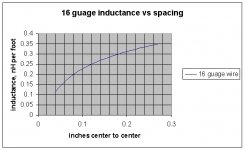
Dale uses a bifilar technique to lower inductance. They wind 350 degrees around the cylindrical form, then turn around and go back, a zig zag pattern simply put onto a cylinder.
On a cylinder, the technique removes the solenoidal component of the winding. On a flat, the wire to wire spacing forms a dipole pattern, the closer they get the better.
If you look at this graph, you can see the effect of cancellation vs the spacing of the pairs for a serpentine pattern.
If you make the resistor using serpentine patterns, and make it 3-d, finishing the wire at the same place in 2d space as the start, you will remove as much inductance as possible.
You'll have to measure the resistor's resonance also..stay at least an order of magnitude below that.
For what you want, it'll certainly be good enough for most measurements in the audio regime. If you need sub nanosecond level loads, your materials and technique will be unacceptable.
There, I could be of service..
Cheers, John
Attachments
poobah said:Thanks John and all,
Back at you a in few days...
I am getting a ruptured disc removed from my back tomorrow... I need to buy slippers of all things! Can you imagine a wookiee in slippers??????????
Whoa. Good luck.
Cheers, John

poobah said:Thanks,
I have arguably one of the best surgeons in the country:
Tip o the day: don't argue wit em..
Good luck, all the best..
John
ps...""The wookiee did NOT find slippers... no 13's or 14's!!!!""
tip #2...use shoe boxes..
- Status
- This old topic is closed. If you want to reopen this topic, contact a moderator using the "Report Post" button.
- Home
- General Interest
- Everything Else
- Calling jneutron, EVA. SY, precision high power resistor