Hello DIYs,
Hope a physicist or another knowledgeable person can help with this....
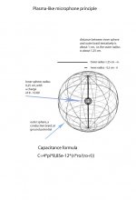
I am considering building a microphone and one of my ideas is to base it on a sort of plasma principle, i.e. to some extent ionizing the air between a charge on a center sphere and an outer sphere - please see attached illustration.
I realize there may be some challenges to this - as described below - so before I venture into the project, I would appreciate informed opinion(s) about the idea. I have briefly described the idea below.
How do I assume it works?
With the inner sphere charged at around 8-10 KV, and the outer sphere's conductive braid grounded, the air molecules between the spheres may be ionized to some extent. When soundwaves move in and out of the outer sphere, these waves having much less ionized air molecules, the amount of ionized molecules inside the sphere varies.
Also, since the inner sphere "discharges" to the surrounding air through a resistor - which means that it is not instantly recharged when it discharges to the new uncharged air that moves inside the outer sphere - the movement of air, i.e. the soundwaves, leads to corresponding charge changes and hence voltage changes on the inner sphere.
These may be output to an electronic circuit e.g. through a transformer or a high voltage capacitor.
So far so good - an idealized view I guess") - and I see some potential obstacles which is why I would appreciate a second opinion:
- and I see some potential obstacles which is why I would appreciate a second opinion:
The spheres constitute a capacitor, yet how do I calculate the capacitance?
Using "normal" capacitance calculations the capacitance between the outer and inner sphere, to my knowledge, would be given by: c=4*pi*å*inner sphere radius*outer sphere radius/(outer sphere radius - inner sphere radius). With the sizes indicated on the illustration the capacitance for these sizes would be about 1 pf using å - the vacuum permittivity. In practice this is a very low, too low, capacitance. So, my question is: when the air is charged in this way with 8-10 KVs does the capacitance change, how much and in which direction? Anybody knows of not too complex formulas for calculating this or has practical experiences in this field?
Another question is if (close to) ionized air can be considered a frequency linear conductor - i.e. more or less identical to normal ground-level air? Anybody with knowledge or experience with this – maybe not too complex formulas? I hope to obtain a very linear close to DC to - around 50 KHz response.
Also if other voltages than 8- 10KV would be preferable?
I realize that air humidity may have a huge impact on the performance of this microphone principle. I hope to be able to compensate this one way or another, maybe by adjusting the polarisation voltage in a simple way.
If any of you knows of other reservations that I should consider before continuing with this project I would appreciate your comments ....
Thanks!
Jesper
Hope a physicist or another knowledgeable person can help with this....
I am considering building a microphone and one of my ideas is to base it on a sort of plasma principle, i.e. to some extent ionizing the air between a charge on a center sphere and an outer sphere - please see attached illustration.
I realize there may be some challenges to this - as described below - so before I venture into the project, I would appreciate informed opinion(s) about the idea. I have briefly described the idea below.
How do I assume it works?
With the inner sphere charged at around 8-10 KV, and the outer sphere's conductive braid grounded, the air molecules between the spheres may be ionized to some extent. When soundwaves move in and out of the outer sphere, these waves having much less ionized air molecules, the amount of ionized molecules inside the sphere varies.
Also, since the inner sphere "discharges" to the surrounding air through a resistor - which means that it is not instantly recharged when it discharges to the new uncharged air that moves inside the outer sphere - the movement of air, i.e. the soundwaves, leads to corresponding charge changes and hence voltage changes on the inner sphere.
These may be output to an electronic circuit e.g. through a transformer or a high voltage capacitor.
So far so good - an idealized view I guess
- and I see some potential obstacles which is why I would appreciate a second opinion:The spheres constitute a capacitor, yet how do I calculate the capacitance?
Using "normal" capacitance calculations the capacitance between the outer and inner sphere, to my knowledge, would be given by: c=4*pi*å*inner sphere radius*outer sphere radius/(outer sphere radius - inner sphere radius). With the sizes indicated on the illustration the capacitance for these sizes would be about 1 pf using å - the vacuum permittivity. In practice this is a very low, too low, capacitance. So, my question is: when the air is charged in this way with 8-10 KVs does the capacitance change, how much and in which direction? Anybody knows of not too complex formulas for calculating this or has practical experiences in this field?
Another question is if (close to) ionized air can be considered a frequency linear conductor - i.e. more or less identical to normal ground-level air? Anybody with knowledge or experience with this – maybe not too complex formulas? I hope to obtain a very linear close to DC to - around 50 KHz response.
Also if other voltages than 8- 10KV would be preferable?
I realize that air humidity may have a huge impact on the performance of this microphone principle. I hope to be able to compensate this one way or another, maybe by adjusting the polarisation voltage in a simple way.
If any of you knows of other reservations that I should consider before continuing with this project I would appreciate your comments ....
Thanks!
Jesper
Attachments
Several points need clarification.
How would the spherical geometry work in light of a planar wave passing through? An impulse, for example, would interact with the volume within the sphere for as long as it takes for sound velocity to traverse the diameter. This would limit the hf response to wavelengths on the order of the diameter give or take a factor or two. Calculate the size required for 50Khz operation.
Also, a loose braid structure will cause field gradients near the braid, tight braid deters sound passing through.
Cheers, John
I would expect capacitance in this geometry to be tiny.
Charging the centre up to high voltage won't change it much. If the plasma becomes dense, so the permittivity is significantly different from that of air, then you will get changes, but this corresponds (at atmospheric pressure) to Arc conditions, rather than the glow discharge you plan on using.
If you work with voltages over a few kV, be very careful for safety. You should also be aware that at 10kV and up you need to worry about x-ray production, and take protective measures. The standard approach of surrounding everything with radiation shields is not convenient for a microphone.
Finally, I don't see how this will work. Consider a sinusoidal air wave. The air flows back and forth. The air wave will displace the plasma slightly out of the sphere as the flow goes forward, and then displace it in the opposite direction when it goes back. Both displacements cause a reduction in the current (you hope), so you have something which responds to the magnitude of air velocity, not the sign. As such it has 100% harmonic distortion.
Appreciate your comments...
Hello - and thank you very much for your replies ....!
Somehow I had hoped that comments like yours would appear.
Although I have a reasonable understanding of audio, waves etc. I am by no means an expert - and appreciate the helpfulness of other people ....
Again thanks!
Jesper
Hello - and thank you very much for your replies ....!
Somehow I had hoped that comments like yours would appear.
Although I have a reasonable understanding of audio, waves etc. I am by no means an expert - and appreciate the helpfulness of other people ....
Again thanks!
Jesper
- Status
- This old topic is closed. If you want to reopen this topic, contact a moderator using the "Report Post" button.