Hi,
I am trying to make a good compensated 100X high voltage probe.
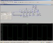
Basically, it is a compensated 99 Meg resitor, but because it is made of a string of resistors, the compensation is not as straightforward as for an usual X10 probe.
R1, 2, 3 and 4 are the HV resistors of the string, complemented by R6 whose role is to introduce some lead effect, to compensate for the lag caused by C1, 2, 3 and 6 (parasitics).
C5 is a fixed HV capacitor. R5 is the input resistance of the scope, and C4 is the sum of the scope's capacitance, cable and adjustable compensation capacitor.
C7, C8 and R7 are the "second order" compensation components.
The values shown give pretty good results with the model (which seems to be pretty close to the reality), but they are not optimum: they are the result of trial and errors.
I would like to find a more "structured" method to arrive at the correct values (without resorting to heavy math).
Does somebody have an idea or a method?
Thanks,
LV
I am trying to make a good compensated 100X high voltage probe.
Basically, it is a compensated 99 Meg resitor, but because it is made of a string of resistors, the compensation is not as straightforward as for an usual X10 probe.
R1, 2, 3 and 4 are the HV resistors of the string, complemented by R6 whose role is to introduce some lead effect, to compensate for the lag caused by C1, 2, 3 and 6 (parasitics).
C5 is a fixed HV capacitor. R5 is the input resistance of the scope, and C4 is the sum of the scope's capacitance, cable and adjustable compensation capacitor.
C7, C8 and R7 are the "second order" compensation components.
The values shown give pretty good results with the model (which seems to be pretty close to the reality), but they are not optimum: they are the result of trial and errors.
I would like to find a more "structured" method to arrive at the correct values (without resorting to heavy math).
Does somebody have an idea or a method?
Thanks,
LV
Attachments
HV probes with bandwidth are very difficult. Philips makes a decent one for 100 MHz at 1 KV in, but it won't handle 1 KV at 100 MHz or even 10 MHz. Tek has made a number of different versions, I have two variations on the 1000X probe. Those are all technique and special construction.
First the resistor is anything but a resistor at higher frequencies, typically high value resistors have significant capacitance .
Second, there is a hazard if you have significant voltage on the input of the string and not being connected to the scope could make a mess of things. The DC will be across all of the caps and insulators at both ends. If you don't need the super high impedance lower the resistors 10X, and a resistor in parallel with the scope and the whole thing will be more manageable.
Modeling is more complex than it seems because the intrinsic caps across the resistors need to be added and the stray caps from component to component need to be added. You have a start on the project.
In the Tek HV design there are "wings" attached to the tip end that wrap loosely (1/2-1" clearance) around the resistor as part of the compensation. They taper out in a funnel shape. The compensator box is pretty complex, I don't have access to its circuit now, but it has 3 separate compensations. Its only good to 10 MHz but can handle 15 KV peaks. I use it for surge testing- 3 KV 20 uS pulses, and its the only thing that will work.
What are you trying to look at?
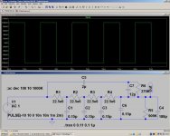
I've made some changes to the original design, and now the equalization is near perfect (ripple&overshoot<1%).
Thanks for answering anyway
For those interested, I've included the amended version; it's simple, yet very effective.
Thanks for answering anyway
This has been addressed in two ways: the original circuit had a small neon bulb across the scope input, limiting the voltage to about 65V (the probe is intended for 5KV max), and now I've added a 11M resistor across the scope too.Second, there is a hazard if you have significant voltage on the input of the string and not being connected to the scope could make a mess of things. The DC will be across all of the caps and insulators at both ends.
I was looking at the striking voltage of fluorescent tubes under various conditions. I used a standard probe rated at 600V, but the peak voltages I measured were in the KV range, sometimes reaching 2KV. And one day, what had to happen did happen and a flashover destroyed the probe. So I'm rebuilding it in a more suitable way.What are you trying to look at?
For those interested, I've included the amended version; it's simple, yet very effective.
Attachments
Looks good. Have you built and tested it? And made sure that you are withing the voltage ratings of the components?
However, being lazy and a little cautious I would get something like one of these P6013 or one of these P6015
New they were/are very expensive but they do work. Used there pretty reasonable. The new P6015A uses silicone and it very expensive. The older P6015 used Freon and the stuff isn't available so the probe needs to be derated but its still over 6KV.
Everyone- Don't play with high voltages unless you know what you are doing and are very careful. They are not forgiving and can ruin your life.
Is a normal 100x probe suitable for use with mains supply voltages?
110/120Vac?
220/240Vac?
400/440Vac?
A 10x probe on 5V/div only goes to +-200V, well short of the >300V on 240Vac mains and the theoretical 622V on 440Vac three phase.
Any links to safe use of oscilloscopes @ these elevated voltages?
Sorry to be slightly off topic.
110/120Vac?
220/240Vac?
400/440Vac?
A 10x probe on 5V/div only goes to +-200V, well short of the >300V on 240Vac mains and the theoretical 622V on 440Vac three phase.
Any links to safe use of oscilloscopes @ these elevated voltages?
Sorry to be slightly off topic.
Even an x100 probe will need a ground clip attached somewhere for a reference, and the neutral circuit may well not be safe. That would be my concern.
I've certainly attached mine to some pretty HV circuits (output transformers, for example), but there was galvanic isolation from the mains.
I've certainly attached mine to some pretty HV circuits (output transformers, for example), but there was galvanic isolation from the mains.
Looking at AC mains is more complex than a single probe issues. First you need probes that are safely rated for the peak voltage. Second, you don't want to tie the scope to the neutral because you can't be certain it is neutral or ground.
The best way is to use something designed to enable looking at power. you can use an active differential probe (tek and other make these) or something like a THS720 with isolated inputs. Both are expensive. Or a pair of HV probes like the Philips ones I mentioned above and a differential input scope. If you don't need the bandwidth you can use a wide band or an audio transformer with a resistive divider on its input to isolate the scope and you from the AC. Use careful construction and layout with lots of clearance between the HV side and the user side.
The best way is to use something designed to enable looking at power. you can use an active differential probe (tek and other make these) or something like a THS720 with isolated inputs. Both are expensive. Or a pair of HV probes like the Philips ones I mentioned above and a differential input scope. If you don't need the bandwidth you can use a wide band or an audio transformer with a resistive divider on its input to isolate the scope and you from the AC. Use careful construction and layout with lots of clearance between the HV side and the user side.
It is built and tested, and it works actually better than the simulation, because I took care to finely tweak the components (doing so in the simulation would make no sense because the model used does not perfectly reflect the reality).Looks good. Have you built and tested it? And made sure that you are withing the voltage ratings of the components?
The resistors are 22Meg VR25 selected for 22.5M actual value. These are metal-glass resistors from Philips rated at 1.6KV.
They are soldered directly end-to-end, without support, and the whole string is inserted in a thick, tight-fitting polythene tubing.
To my knowledge, all X100 probes have ratings in excess of 1KV, so they should be OK, even at 440V.Is a normal 100x probe suitable for use with mains supply voltages?
Some probes and scopes are specially designed for "live earth" measurements : the scope has no metal or conductive part accessible, and the outer part of the BNC (the bayonnet ring) is made of composite.
LV
- Status
- This old topic is closed. If you want to reopen this topic, contact a moderator using the "Report Post" button.
- Home
- General Interest
- Everything Else
- HV Probe compensation