Hello, I was so lucky, that i got a '' pro alucut 80teeth ø254mm '', and i have tried to attach it to an '' Variac 0-230 transformer '', so to lower the rpm's to around 1700rpm, for idle cut with this circularsaw.
Well it's working allright, but the problem is, that the saw is loosing some power when doing it with a variac.
Does anyone here know how the regulators on pro circular saw's work ???, ore another cheap way of doing this ???
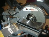
I have attached a picture of my saw, and i think it's a serie motor, where the 'stator windings' is in serie with the 'rotor' via the brushes.
EDIT : It's for cutting Alu ofcause
Well it's working allright, but the problem is, that the saw is loosing some power when doing it with a variac.
Does anyone here know how the regulators on pro circular saw's work ???, ore another cheap way of doing this ???
I have attached a picture of my saw, and i think it's a serie motor, where the 'stator windings' is in serie with the 'rotor' via the brushes.
EDIT : It's for cutting Alu ofcause
Attachments
A servo controlled variac or rheostat is an option. Ideally what you need to do is to lower the ac frequency. This is complicated.
I think what you could do is shunt hot threw a 0.065ohm shunt. As the current increases (motor load) the voltage drop over the shunt will raise. Rectify and filter this drop, add a bias (speed control), and use it to control a TRIAC.
 I thought of that all be myself
Edit : Wait, no rectify?
I think what you could do is shunt hot threw a 0.065ohm shunt. As the current increases (motor load) the voltage drop over the shunt will raise. Rectify and filter this drop, add a bias (speed control), and use it to control a TRIAC.
I thought of that all be myself Edit : Wait, no rectify?
lykkedk said:Well it's working allright, but the problem is, that the saw is loosing some power when doing it with a variac.
A smaller blade with a thin kerf will have a slower tooth speed and not be as much a draw on the saw. Are you using a cutting lubricant?
Agreempmarino said:I dunno about controlling the speed: But I'd lose that glove - it's more danger than protection IMHO.
When it comes to AC motors like power saw motors, the RPM is determined by the frequency of the local power grid ... usually either 50 or 60 Hertz / cycles per second.
Trying to control the RPM of an regular AC motor by using a Variac can be quite dangerous ... not only will the RPM get out of control (while trying to stay within ~ 85% of "ideal", synced grid based RPM) the power will become erratic and "drop phasing" with the power grid = intemittent speed changes and power fluctuations = burned motor windings or worse.
Most AC motors with variable speed controls use a switching power supply that takes the grid power and frequency and converts it to a pulse width modulation AND frequency variation to achieve speed / RPM control ...
Speed control.
Most power tools have a simple scr or triac speed control in them. Usually this circuit senses load and increases output to compensate. The motor on this saw should be a universal type so it could be run off of dc or ac. The hardware stores here sell replacement variable speed triggers for power drills for around 20 USD. I would think you could wire one to the saw and make an adjustable stop to set speed.
Dremel used to sell a plug in box to do this, I do not know if they still sell them. I think there are some schematics for such things on the internet. Need a big scr, a few resistors, a couple of caps, and a rheostat. Regards, Steve
Most power tools have a simple scr or triac speed control in them. Usually this circuit senses load and increases output to compensate.
I think i will try this, but the reason i didn't bother before, was that i thought it would give the same problem, cause the Triac cut's out part of the sinewave to simulate freq. inc / decresment... am i right here ?
The motor could be run of a dc-regulator i am sure, but i don't know how much it would need then. Actually the best (And most expensive) is ofcause a real freg. converter...
About lubrication, i am interessted in knowing more !!!
Jesper
lykkedk said:
The motor could be run of a dc-regulator i am sure, but i don't know how much it would need then. Actually the best (And most expensive) is ofcause a real freg. converter...
About lubrication, i am interessted in knowing more !!!
Jesper
There is no reason to use frequency converter with universal current motor (a.k.a. series wound dc motor)
Just control the voltage: triac, variac or whatever you got. You can even run it perfectly fine with dc, it spins right direction even with reverse polarity.
Most drill and saw motors are actually universal motors (rather than induction motors as described above)- they are basically a series wound dc motor and because the field and armature current both alternate with the mains, the motor spins in the same direction with each half wave.. The torque is inversely proportional to speed.
I have seen kits to control the speed of these motors, basically the technique involves switching with a triac/SCR with a circuit designed to trigger based on motor back emf (generated voltage which is proportional to speed). There's DIY projects about, I remember one in ETI (australian electronics magazine) circa 1980's, but I don't know the project #.
I have seen kits to control the speed of these motors, basically the technique involves switching with a triac/SCR with a circuit designed to trigger based on motor back emf (generated voltage which is proportional to speed). There's DIY projects about, I remember one in ETI (australian electronics magazine) circa 1980's, but I don't know the project #.
After considering things, i think the most (and best) thing to do is, to give the field it's own supply, and then regulate the supply on the armature. If this will work as a DC-motor regulation, i will then have no powerloss from 0 - 5000rpm...
I am just now investigation how the stuff is made in real pro machines, so that i could get it right.
What about lubrication ??? no need ???
Jesper.
Don't get exited there is no hands in them, i allready lost them....
I am just now investigation how the stuff is made in real pro machines, so that i could get it right.
What about lubrication ??? no need ???
Jesper.
I dunno about controlling the speed: But I'd lose that glove - it's more danger than protection IMHO.
Don't get exited
there is no hands in them, i allready lost them....Hi,
the triac and diode methods reduce the output torque of the motor.
Reduced torque results in reduced speed and that leads to reduced cooling (slow fan speed). The overall effect is very variable speed as the load changes (pushing the workpiece faster or slower) and burnt out motors.
the triac and diode methods reduce the output torque of the motor.
Reduced torque results in reduced speed and that leads to reduced cooling (slow fan speed). The overall effect is very variable speed as the load changes (pushing the workpiece faster or slower) and burnt out motors.
lykkedk wrote
Don't do it, u will burn the motor as its individual winding ratings will not be known. Moreover a properly implemented DC shunt motor has a field failure relay.
IIRC speed is inversely proportional to field current.
I recall seeing a phase control circuit on the net with SCRs that is slaved to a small light dimmer. May be a good option and easy build.
Gajanan Phadte
After considering things, i think the most (and best) thing to do is, to give the field it's own supply,
Don't do it, u will burn the motor as its individual winding ratings will not be known. Moreover a properly implemented DC shunt motor has a field failure relay.
IIRC speed is inversely proportional to field current.
I recall seeing a phase control circuit on the net with SCRs that is slaved to a small light dimmer. May be a good option and easy build.
Gajanan Phadte
High power slave...
http://www.edn.com/article/CA629309.html?spacedesc=designideas
Enjoy
Gajanan Phadte
http://www.edn.com/article/CA629309.html?spacedesc=designideas
Enjoy
Gajanan Phadte
- Status
- This old topic is closed. If you want to reopen this topic, contact a moderator using the "Report Post" button.
- Home
- General Interest
- Everything Else
- Circular saw rpm regulator...