Unless there's a very strange test signal involved, I'd expect the currents to be correlated anyway.
Only two sinusoids with the same phase and frequency could be regarded as correlated in order to allow for
Itot = Ia + Ib
otherwise one has to refer to geometrical summing.
Regards
Charles
Hmmm. Rather than fretting about differences in power (necessitating consideration of whether the currents are correlated or uncorrelated), try it this way:
If a single driver is fed from a perfect source (zero resistance) via a finite resistance then the voltage dropped across that resistance is an error voltage that is subtracted from the amplifier output voltage. If the driver is a pure resistance, then the error voltage simply represents constant attenuation at all frequencies. If the driver has a changing impedance, then the error voltage shows up as a deviation in amplitude vs frequency response. This effect is particularly common with single-ended triode amplifiers because they rarely have feedback, leaving their output resistance at half the load resistance.
Consider a loudspeaker using two drivers, with each section of the crossover fed from a perfect source (zero resistance) via individual source resistance (biwiring). The error voltage across the series resistance is the same as the first instance and simply causes a frequency response error. Even if one driver draws a very large and heavily distorted current, it does not affect the other.
Now consider a loudspeaker with two drivers but each section of the crossover fed from a shared source resistance. If one driver draws a large and nonlinear current (perhaps because its coil is jumping out of the gap), the error voltage reflects that nonlinearity and is not only subtracted from the driver produced it, but also from the other driver.
Remembering that distortion always means the generation of higher harmonics, monowiring means that a bass loudspeaker having inherent acoustic filtering of higher frequencies is now allowed to act as a generator and create an error voltage in series with a tweeter perfectly capable of reproducing that distorted error voltage.
Does all this really matter? I think it does. Many years ago, I had a pair of expensive studio monitors (£6k) on sale or return. I diligently spent all day listening to them, then went home and listened to my LS3/5a. By comparison, the LS3/5a sounded muddy. They were so bad that I felt I couldn't listen to them again, so I decided I had nothing to lose by modifying them. I opened them up to see if I could find anything suspicious. The main thing I found was a very poor PCB layout on the crossover where both signals passed through a very narrow track having significant resistance. I rerouted wiring to avoid that narrow track and the loudspeakers were markedly improved. (Oh, and we bought the PMC MB1.)
phase_accurate said:
Only two sinusoids with the same phase and frequency could be regarded as correlated in order to allow for
Itot = Ia + Ib
otherwise one has to refer to geometrical summing.
Regards
Charles
Ah, I see where you're thinking.. You are assuming phasor notation..
Forget the phase...while the phase is certainly of concern as far as the load dissipation at any instant, note that I have not discussed the current phase with respect to the voltage.
Merely that the real component of dissipation is altered.
Perhaps using DC for one current will help you?
Cheers, John
phase_accurate said:
Only two sinusoids with the same phase and frequency could be regarded as correlated in order to allow for
Itot = Ia + Ib
otherwise one has to refer to geometrical summing.
Regards
Charles
Not to drag things off topic, but a non-zero correlation can lie anywhere between 0 and 1; as you say, a vector sum is appropriate, but it will not be zero except for special circumstances like jneutron's example. For a musical signal, the upper harmonics will be correlated with the fundamental to a pretty high degree- this has major implications in crossover design.
For a musical signal, the upper harmonics will be correlated with the fundamental to a pretty high degree- this has major implications in crossover design.
Yes but we are discussing some strange loss of power which is basically a non-issue.
EC1080 made a good description of how bi-wiring works.
Regards
Charles
I cringe at discussing the more complex system you describe. While certainly the end result, it confounds the simplicity of the analysis I present.
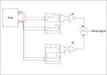
Here is a test setup to establish/refute my assertion...enjoy.
1. Put 1 ampere 10Khz into this system. Balance the IA gains to null the error output.
2. Inject 1 ampere at 20 hz. Now, what does the error become?
That error is the difference between biwiring and monowiring. If it is not present, there is no difference..
Man, I love testable hypothesis...anybody game to try it??
Cheers, John
Attachments
phase_accurate said:
Yes but we are discussing some strange loss of power which is basically a non-issue.
Regards
Charles
Hmm..
It is not a strange loss of power, it is a rather well defined one. Since it is a result of the product of two sines, it has a zero integral power (meaning the RMS losses are unchanged), but is just a time varying modulation of the wire losses.
It is indeed strange in that half the time, this 2AB dissipation is negative..but that is not a problem because the driving losses always exceed the value of the 2AB component, so the instantaneous loss never goes negative..
"Non issue" is not shown..it may yet prove to be a non issue, but that has not been demonstrated yet.
The test setup I define can easily be injected with music to determine what exactly comes out in the "error wash". One only has to match the components very accurately across the audio bandwidth to eliminate tolerance generated errors.
Cheers, John
jneutron said:Now, lets examine a specific setup, that being one amp with both moniwiring and biwiring attached to the same output.
I've established system boundaries around the speakers. The only energy input into those boundaries is the wires.
With only one amplifier, both speakers are seeing the exact same terminal voltage at the amp end, that removes amplifier "reactions" as the source of any difference.
From the previous post, it is clear that the powerloss between the amplifier and both speakers is different, the C, or monowire case, having that 2AB loss component that the upper biwire set doesn't have.
The assumption that biwiring makes NO DIFFERENCE, means that even though the lower speaker DOES NOT SEE THE SAME POWER INPUT because the losses in the feedwires are different, the speaker still gets the same power?
The assumption that biwiring makes no difference violates the first law of thermodynamics.
Cheers, John
Are there audible differences between the wiring methods?
There are certainly differences mathematically and at a molecular-atomic level.
But can our caveman brain and jiggling tympanic membranes tell the difference?
Some claim there is. Some claim there isn't. I do not know.DCPreamp said:Are there audible differences between the wiring methods?
Well, I'm not worried bout the molecular-atomic level, sheesh I'm not that much of a geek...(am I??)DCPreamp said:There are certainly differences mathematically and at a molecular-atomic level.

Don't know. If we see a measurable difference at the tweets as per my test diagram, I'd suspect image (localization) issues at best. I do not believe audibility tests consider how we localize that much. But for the purposes of the test proposed, audibility is off topic..(yah, I know, it's an audio site...details, details...DCPreamp said:But can our caveman brain and jiggling tympanic membranes tell the difference?

Cheers, John
Hi John,
How embarrassing. Let me see if I can parse my thoughts into actual language. My question was, is there a situation in which an electron can attach to a dielectric atom, at the normal outer orbital charge threshold of that atom, and through some format of matrix with other electron states in the surrounding atoms of a dielectric, allow another, lower threshold charge state orbit to become available? If this is possible what are the factors that would contribute to this event.
"Dipole electrons" referred to the emission of an electron from a dielectric dipole structure, or perhaps only a change in orbital angle of rotation, which I admit I have a pretty hazy picture of, when the "other end" of the dielectric dipole accepts an electron or changes it's orbital angle of rotation? The "signaling" across a dielectric, that allows capacitively coupled signals to occur.
"Electron threshold level" referred to lower charge values, of electrons that carry a low amplitude portion of a bulk, coherent, information packet, as it attaches to a dielectric, at a static moment.
Could you expand upon the mechanism you noted with "It is not concerned with what the signal actually is, but the instantaneous value added to historical charging of the dielectric"? What is the historical charging of a dielectric from and what are the implications for retention of the low charge electrons, remaining as a coherent part of an information packet, at an electrostatic moment?
Thanks,
Bud
jneutron said:If we see a measurable difference at the tweets as per my test diagram, I'd suspect image (localization) issues at best.
It's been so many years since I crunched those numbers it may have been on punch cards but your test setup will show a difference in the x-over region due the different impedances terminating the wires/wire feeding the tweeter. Again so long ago but I recall, using a realistic figure of 0.1 ohm for connectors and wire, depending on x-over order it could be in the 0.1 - 0.2 dB range, enough to potentially swamp more sutble effects.
rdf said:
It's been so many years since I crunched those numbers it may have been on punch cards but your test setup will show a difference in the x-over region due the different impedances terminating the wires/wire feeding the tweeter. Again so long ago but I recall, using a realistic figure of 0.1 ohm for connectors and wire, depending on x-over order it could be in the 0.1 - 0.2 dB range, enough to potentially swamp more sutble effects.
Ah, I'm aware of that analysis, I believe even Leseuf has that on his site.
No, my analysis is not at that frequency, but rather at frequencies far removed from the crossover point interaction.
Cheers, John
- Status
- This old topic is closed. If you want to reopen this topic, contact a moderator using the "Report Post" button.
- Home
- General Interest
- Everything Else
- "audiophools"