I´m currently servicing my AVO CT-160 Tube Tester (works fine) but I have a big problem as I don`t know how to remove the knobs.
The manual says:
"To remove any knob, remove 6BA screw and spring washer. To remove knob spindle and skirt, release locking pin. .........................."
This sounds fairly easy but whatever I do and which knob I try, there is no chance to "release" those locking pins.
All of this pins fit so tight like they seem to be welded into the knob spindle.
I tried to insert fine oil and with a small hammer and a "snap through" (don`t know if this is the right word).
This damn pins just don`t move...
I did not want to beat too hard because I fear about damaging the meter.
I tried to heat the knob spindle - again nothing.
If those pins don`t come out I can`t remove the knob spindle. If I can`t remove the knob spindle I can`t get access to the switch nut and without this I can`t remove the switch or pot which is underneath the chassis.
Usually I get this sort of things done one way or another but in this case I seem to be lost and about to loose my patience ....
If anybody out there could help me it would be very appreciated.
Maybe there is a special trick....
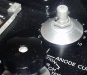
attached a picture of the knob with the upper part already removed:
The manual says:
"To remove any knob, remove 6BA screw and spring washer. To remove knob spindle and skirt, release locking pin. .........................."
This sounds fairly easy but whatever I do and which knob I try, there is no chance to "release" those locking pins.
All of this pins fit so tight like they seem to be welded into the knob spindle.
I tried to insert fine oil and with a small hammer and a "snap through" (don`t know if this is the right word).
This damn pins just don`t move...
I did not want to beat too hard because I fear about damaging the meter.
I tried to heat the knob spindle - again nothing.
If those pins don`t come out I can`t remove the knob spindle. If I can`t remove the knob spindle I can`t get access to the switch nut and without this I can`t remove the switch or pot which is underneath the chassis.
Usually I get this sort of things done one way or another but in this case I seem to be lost and about to loose my patience ....
If anybody out there could help me it would be very appreciated.
Maybe there is a special trick....
attached a picture of the knob with the upper part already removed:
Attachments
Another suggestion...
The pins look like a different metal from the shaft. Over time, electro-chemical activity may have caused build up of metal salts. Perhaps some chemist could suggest a suitable solvent. When losened, you may still have to fabricate a tool that will "press" the pin out.
Please don't use a hammer
The pins look like a different metal from the shaft. Over time, electro-chemical activity may have caused build up of metal salts. Perhaps some chemist could suggest a suitable solvent. When losened, you may still have to fabricate a tool that will "press" the pin out.
Please don't use a hammer
You could always drill them out.
I have thought of this already.
But it isn`t that easy.
It would only work (maybe) for the knobs located nearby the chassis edges.
For the other knobs located more in the center of the chassis it is almost impossible to drill them out as the pins are located at a level of about only 2cm above the chassis.
As it is unlikely to find a 3mm diameter drill with a length of 200mm this means that a suitable drilling machine may have only about 4cm diameter (and this only without interfering with other knobs or things on the chassis). My Dremel like machine is already a bit bigger.
Even if I could manage it somehow this work would really be a mess and I`d rather avoid this.
That`s true! The pins are made of something like steel whereas the knob spindle seem to be aluminium.The pins look like a different metal from the shaft.
I just don`t get it why this pins have to be the way they`re. Why not just a srcew as it would be normally used for such a knob
 Does this kind of thing belong to black British humour?
 I think this is spot on.Over time, electro-chemical activity may have caused build up of metal salts.
Well I hope, maybe someone.....Perhaps some chemist could suggest a suitable solvent.
I have abandoned the idea already (at least with the meter still mounted in the chassis).Please don't use a hammer

Thanks for the responds so far!
Does this kind of thing belong to black British humour?
Anything can happen north of the Veal sausage equator
Roll pins like that usually have a coating which is pretty effective in preventing corrosion. You've got a mechanical problem.
I'm no expert, but Bill's solution seems like a good one. Maybe a C clamp might be better then pliers. I'm feeling lazy at the moment, so I'll leave it to you to search McMaster-Carr or MSC catalogs to see if there's a suitable extraction tool- if it's cheap, buy it. If it's expensive, try to improvise it.
I'm no expert, but Bill's solution seems like a good one. Maybe a C clamp might be better then pliers. I'm feeling lazy at the moment, so I'll leave it to you to search McMaster-Carr or MSC catalogs to see if there's a suitable extraction tool- if it's cheap, buy it. If it's expensive, try to improvise it.
yet another AVO problem
Thanks for all the suggestions.
I`ll leave to solve that problem later, because meanhwhile I`ve got another and more urgent problem with that machine (I`m going to hate it).
Later I`ll try what SY suggested and to make a special clamp in order trying to press those pins out.
I don`t know if my my new problem justify to open another AVO thread but I think I try it here first.
Does somebody know how to adjust the failure "protection" relay on the AVO CT-160?
The (poor, as other things) manual only say it seldom require maintenance but not how to adjust it or how it works when it is okay.
I was almost completely through to calibrate the tester (everything fine and after some adjustments very precise & inside specs) and I wanted to test this relay function finally. I bought a new bulb (as the existing in the circuit was defective) and which is part of this protection circuit (it was quite hard to find a suitable bulb and I only got one in blue not in red, anyway).
When I short the anode-cathode path at the top panels connectors the relay works at about 75V anode voltage .
The bulb lights as it should and I can hear the relay "buzzing ".
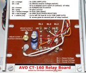
But after a few seconds there was blue smoke and it almost burned a precision resistor (R10= 200R +/- 0.5%) on the "board".
The resistor seems to be slightly out of tolerance now and likely I`ll have to replace it (and as this resistor is part of the anode voltage current measuring circuit, likely I´ll have to repeat some parts of the calibartion procedure also )
I thought the protection circuit is there for that purpose and not to burn parts. At least I thought that it protects until one of the fuses blow (to me it seems that the two 2A value fuses are much too high to be effective, at least at 230V mains voltage). Obviously I seem to be wrong and the tester has to be switched off immediately (wether this or the relay is misadjusted) after a failure occur but I can`t find such a warning in the manual.
Yesterday I spent 4 hours to disassemble the relay "board" and to understand which part is what (of course not mentioned in the manual) and how it works.
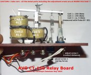
The relay is a rare mechanical construction of a seesaw contact, 3 coils on an U-shaped core (with the core as part of the contact), springs and 2 adjustment srews.
As far I can judge this, the relay and coils (*) are okay and the thing just needs to be adjusted.
(*) two of the three coils have 255 Ohm resistance, the third only about 5 Ohm (these measures are nowhere mentioned in the manual) so I thought the low ohms coil may have burned also and so I desoldered and unwound it to see if this is the case (10m of wire ).
).
The wire of the coil seem to be okay as unwound it measures the same.
My question is if somebody know how to adjust the protection circuit without burning parts and if the tester have to be switched off immediately after a fault even when the relay is properly adjusted?
Thanks for all the suggestions.
I`ll leave to solve that problem later, because meanhwhile I`ve got another and more urgent problem with that machine (I`m going to hate it).
Later I`ll try what SY suggested and to make a special clamp in order trying to press those pins out.
I don`t know if my my new problem justify to open another AVO thread but I think I try it here first.
Does somebody know how to adjust the failure "protection" relay on the AVO CT-160?
The (poor, as other things) manual only say it seldom require maintenance but not how to adjust it or how it works when it is okay.
I was almost completely through to calibrate the tester (everything fine and after some adjustments very precise & inside specs) and I wanted to test this relay function finally. I bought a new bulb (as the existing in the circuit was defective) and which is part of this protection circuit (it was quite hard to find a suitable bulb and I only got one in blue not in red, anyway).
When I short the anode-cathode path at the top panels connectors the relay works at about 75V anode voltage .
The bulb lights as it should and I can hear the relay "buzzing ".
But after a few seconds there was blue smoke and it almost burned a precision resistor (R10= 200R +/- 0.5%) on the "board".
The resistor seems to be slightly out of tolerance now and likely I`ll have to replace it (and as this resistor is part of the anode voltage current measuring circuit, likely I´ll have to repeat some parts of the calibartion procedure also
)I thought the protection circuit is there for that purpose and not to burn parts. At least I thought that it protects until one of the fuses blow (to me it seems that the two 2A value fuses are much too high to be effective, at least at 230V mains voltage). Obviously I seem to be wrong and the tester has to be switched off immediately (wether this or the relay is misadjusted) after a failure occur but I can`t find such a warning in the manual.
Yesterday I spent 4 hours to disassemble the relay "board" and to understand which part is what (of course not mentioned in the manual) and how it works.
The relay is a rare mechanical construction of a seesaw contact, 3 coils on an U-shaped core (with the core as part of the contact), springs and 2 adjustment srews.
As far I can judge this, the relay and coils (*) are okay and the thing just needs to be adjusted.
(*) two of the three coils have 255 Ohm resistance, the third only about 5 Ohm (these measures are nowhere mentioned in the manual) so I thought the low ohms coil may have burned also and so I desoldered and unwound it to see if this is the case (10m of wire
).The wire of the coil seem to be okay as unwound it measures the same.
My question is if somebody know how to adjust the protection circuit without burning parts and if the tester have to be switched off immediately after a fault even when the relay is properly adjusted?
No, you don't need to make anything special at all to get those pins out. You need a small "G" clamp (or even a "C" clamp!) and a spacer with an internal diameter bigger than the pin and the same length or longer than the pin. Dangle the spacer over one end of the pin. Fit the clamp over the two and use the clamp to drive the pin through the shaft and into the spacer. Once the pin is flush with the shaft, you won't be able to go any further, but by then you will have enough pin sticking out the other side (and you'll have got it moving) that a big pair of pliers should be able to pull it the rest of the way. Penetrating oil might help.
The more I find out about AVO's construction techniques, the less I like them...
The more I find out about AVO's construction techniques, the less I like them...
originally posted by EC8010
No, you don't need to make anything special at all to get those pins out. You need a small "G" clamp (or even a "C" clamp!) and a spacer with an internal diameter bigger than the pin and the same length or longer than the pin. Dangle the spacer over one end of the pin. Fit the clamp over the two and use the clamp to drive the pin through the shaft and into the spacer. Once the pin is flush with the shaft, you won't be able to go any further, but by then you will have enough pin sticking out the other side (and you'll have got it moving) that a big pair of pliers should be able to pull it the rest of the way. Penetrating oil might help.
Thanks for the tips! I`m now much more confident that I`ll get the pins out. Anyway this is more worthwile to try first, before drilling them out.
I just don`t have such small clamps. The smallest I have are about 30cm for wood work. I`ll ask my brother if he has something a bit more suitable
.Seems that currently I have to learn the same lesson...The more I find out about AVO's construction techniques, the less I like them...
Meanwhile I reassembled the relay board. At this occasion I made some photos. As I don`t want to loose all those messy notes I made during the last days (as it happens to me frequently), I spent this evening in learning how to use a graphics program to join my notes with the photos.
I´m very satiesfied with the result, maybe it`s for use for others too.
Attachments
- Status
- This old topic is closed. If you want to reopen this topic, contact a moderator using the "Report Post" button.
- Home
- Design & Build
- Equipment & Tools
- AVO CT-160 Tube Tester - how to remove knobs?? - please help