Hi there,
Along the years I have designed many testers and measuring instruments, all perfectly sound and functional technically speaking, but sometimes more, let's say, questionable or dubious from an actual usefulness perspective.
Here is a first example of such a wacky tester, a "Wiring Anomaly Detector": it lights a LED when the cable it is connected to has some kind of impedance discontinuity, like a change in the characteristic impedance, mode (balanced/unbalanced), a bridge tap or similar:
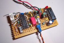
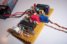
Meet the Stufinator:
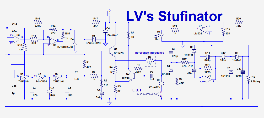
The heart of the circuit is a network analyser on 2 chips: U1 to 3 form a ring oscillator having its supply voltage modulated by a triangle wave generated by U5/U6.
The Vdd varies from ~2 to 5V, causing a frequency variation of ~5 to 20MHz.
The nice thing with this oscillator is that the output is almost sinusoidal, and with just a small additional filtering + equalization, is also almost constant in amplitude wrt. frequency.
This frequency sweep is applied to a directional bridge formed by R4 to 6, and the (properly terminated) line under test.
Q2 extracts the return loss signal from the line, and presents it on its collector.
For progressive wave conditions, this signal is small and is representative of the static impedance mismatch, but when a discontinuity is present, stationary waves are created, and the pattern of these stationary waves varies with frequency, generating an amplitude modulation of the recovered signal.
The signal is first RF-detected, thanks to D1, and its low-frequency ripple is amplified by U4 and then rectified in the LF detector D2/D3.
When the resulting DC exceeds a threshold set by the trimmer, the comparator U7 lights red LED.
D6 provides a direct bypass path to also light the LED under extreme mismatch conditions, like a short or open connection.
This tester could have some usefulness for the troubleshooting of installations supporting relatively fast signals, like video, DSL, ethernet, etc, but for audio it is essentially non-relevant.
Nevertheless, I am sure it will delight many "Audiophiles": it will allow them to make sure their signals follow a smooth, unimpeded path
In principle, the circuit is inherently unbalanced, but since it is a very small, battery-operated device, its capacitance wrt. the ambient space is negligible, and it will work perfectly well for balanced signals too.
The reference impedance and the line termination have to match the characteristic impedance: 75Ω for video/TV, 50Ω for RF, 100Ω for ethernet, 120Ω for DSL, etc.
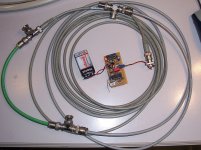
Here is an example: the tester is configured for 50Ω and connected to two cascaded 50Ω cables of several meters. When the circuit is homogeneous, the LED remains off:
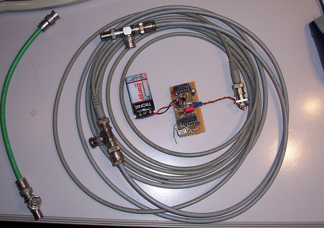
but when a small (23cm) 75Ω section (green cable) is inserted, the LED lights up:

These are relatively harsh conditions, because the 75/50 mismatch is moderate and is in pass-through, but for easier conditions, like a bridge tap or more abrupt impedance changes, the sensitivity is even higher.
Have fun!
Along the years I have designed many testers and measuring instruments, all perfectly sound and functional technically speaking, but sometimes more, let's say, questionable or dubious from an actual usefulness perspective.
Here is a first example of such a wacky tester, a "Wiring Anomaly Detector": it lights a LED when the cable it is connected to has some kind of impedance discontinuity, like a change in the characteristic impedance, mode (balanced/unbalanced), a bridge tap or similar:
Meet the Stufinator:
The heart of the circuit is a network analyser on 2 chips: U1 to 3 form a ring oscillator having its supply voltage modulated by a triangle wave generated by U5/U6.
The Vdd varies from ~2 to 5V, causing a frequency variation of ~5 to 20MHz.
The nice thing with this oscillator is that the output is almost sinusoidal, and with just a small additional filtering + equalization, is also almost constant in amplitude wrt. frequency.
This frequency sweep is applied to a directional bridge formed by R4 to 6, and the (properly terminated) line under test.
Q2 extracts the return loss signal from the line, and presents it on its collector.
For progressive wave conditions, this signal is small and is representative of the static impedance mismatch, but when a discontinuity is present, stationary waves are created, and the pattern of these stationary waves varies with frequency, generating an amplitude modulation of the recovered signal.
The signal is first RF-detected, thanks to D1, and its low-frequency ripple is amplified by U4 and then rectified in the LF detector D2/D3.
When the resulting DC exceeds a threshold set by the trimmer, the comparator U7 lights red LED.
D6 provides a direct bypass path to also light the LED under extreme mismatch conditions, like a short or open connection.
This tester could have some usefulness for the troubleshooting of installations supporting relatively fast signals, like video, DSL, ethernet, etc, but for audio it is essentially non-relevant.
Nevertheless, I am sure it will delight many "Audiophiles": it will allow them to make sure their signals follow a smooth, unimpeded path
In principle, the circuit is inherently unbalanced, but since it is a very small, battery-operated device, its capacitance wrt. the ambient space is negligible, and it will work perfectly well for balanced signals too.
The reference impedance and the line termination have to match the characteristic impedance: 75Ω for video/TV, 50Ω for RF, 100Ω for ethernet, 120Ω for DSL, etc.
Here is an example: the tester is configured for 50Ω and connected to two cascaded 50Ω cables of several meters. When the circuit is homogeneous, the LED remains off:
but when a small (23cm) 75Ω section (green cable) is inserted, the LED lights up:
These are relatively harsh conditions, because the 75/50 mismatch is moderate and is in pass-through, but for easier conditions, like a bridge tap or more abrupt impedance changes, the sensitivity is even higher.
Have fun!
Attachments
Last edited:
- Status
- This old topic is closed. If you want to reopen this topic, contact a moderator using the "Report Post" button.