What are you going to use it for?
For most of my career at Motorola I designed radio equipment. For the last 12 years I worked in a research group inventing new technology. As with any IC or component company, once we designed a unique component, circuit, or new concept, we had to "sell it" to the radio product development teams. Essentially we had to compete against the other vendors trying to sell their new tech to our product groups. Until the last two years it was my job to design a test board (EVB) or other means of showcasing our tech. Many times I would design a complete functional two way radio with our chip or other tech as the show piece. In doing this I came up with all sorts of cool ideas for radio design, but I was bound by "employment contract" not to do anything outside of Motorola that could be construed in any way as "similar" to anything that Motorola was involved in.
Now that I am not bound by that agreement, I am going to explore some of my ideas, and if a cool ham radio gizmo just happens, well.....
In reality that stuff came so easy to me just 3 or 4 years ago. I could sit down at the computer with one of our new chips, and some PCB design tools, and poof within a month or two I could have a prototype in hand, and more often that not, it would work. I'm just curious if I can still do that. I had 3 of these exact same generators on my desk at Mot. In the past two years, I have nearly recreated the lab I had at work about 4 years ago. Mostly by "bottom feeding" on Ebay or hamfests and then fixing the stuff up. If I wind up with too many fancy signal generators, I will sell the extras to pay for this effort.
If I don't take a stab at it soon, technology will outrun me. All the chips and tech I used in my last prototype radio are already obsolete and that was just 4 years ago. Note that at Mot, we had our own PC board fab, and an automated SMD assembly line, and people to get you just about any part made anywhere in the world, a complete machine shop with CNC capability for metal or plastic.
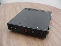
They asked me for a test radio to showcase a fast data protocol out team had invented. They wanted a powerful trunk mounted mobile unit. The picture shows what I gave them. The housing was CNC carved from a solid slab of aluminum. I designed the circuitry, and laid out the PC boards, they were fabbed and assembled in house.
I'm thinking the inductors balance out the parasitic capacitance
Each SMD part, and the PC board pads that it is placed on have a parasitic capacitance, both in parallel with the part, and to ground. If the part is a resistor of more than a few hundred ohms the associated capacitive reactance will tend toward making its value appear lower as the frequency increases. The smaller pads have higher value resistors in the shunt element, thus requiring some help. The meandering inductance cancels this effect.
Can it be done in the 'on paper' design or is it by empirical testing of a built prototype?
Real paper, no. A computer simulation, yes, provided the models are correct. I have seen things done both ways. I knew engineers that would characterize everything, make computer models and simulate things well enough to get good results. This make sense when you are making millions of cell phones and you have other people making all the computer models. When I was making one off prototypes, and I could get a two layer PC board made in 4 hours, or a multilayer in a day, I just slapped down several "best guesses" on a test board and picked the best one.
The old 500 MHz Kay attenuators had a metal strap that was "tuned" by bending while observing the trace on a network analyzer.
Attachments
There's also a huge amount of empirical knowledge to draw on for this stuff. Microwave circuits are just resistors, capacitors, inductors and transistors same as anywhere else, and every component has a model that you can design around. https://www.microwaves101.com is a good start for reading up on this stuff.
It's a neat website I'd likely never have bumped into otherwise. If the project planning list didn't already have a phono stage, a buffered passive line level XO, fixing an old tuner and working out an amp right now I could stop soldering and get drawn right in. I've always wondered about rf stuff. Thanks for the introduction.
In doing this I came up with all sorts of cool ideas for radio design,
Now that I am not bound by that agreement, I am going to explore some of my ideas, and if a cool ham radio gizmo just happens, well.....
Was all your work done on Ham radio? I was thinking of asking you what you knew about FM pulse count detectors . . . .
Now that sounds more like the sort of technology I can relate to!The old 500 MHz Kay attenuators had a metal strap that was "tuned" by bending while observing the trace on a network analyzer.
An amp I built a few years ago had a 6336 output tube that liked to go Pow (!!) with a grid short after being well warmed up. Though all advice was to ditch it I just couldn't stand the idea of wasting a tube that looking through the glass, so obviously had all the right parts but just wasn't working like it should.
I figured the cause of the short was the grid sagging just enough to close a gap somewhere, so after taking a good look at the tube and guessing which part of the grid was going which way, I stood the amp on its side so the grid would sag in the opposite direction. I don't have measured proof that my guess at the cause was right but the manoeuver was successful in stopping the shorts and after a year of playing it that way ten years later the tube still works without incident, now when upright.
Was all your work done on Ham radio?
No, none at all. Even though Motorola owned Yaesu (a major ham radio player) for a few years, Motorola made it clear that they were not interested in ham radio and actually frowned on our ham radio club activities. Mot acquired Yaesu in the process of buying their parent company Vertex Standard. They eventually gave control of Yaesu back to the Japanese family that originally started the company.
I worked on the public safety hand held two - way radio product line (police and fire walkie talkies) for most of my career. I worked in an off campus think tank operation for about 3 years in the mid 90s, and worked in the team that designed the Nextel (iDEN) "walkie talkie)"phones for about 6 years before joining the research group developing advanced public safety technology.
6336 output tube that liked to go Pow
I have had issues with the same tubes. The cathode in that tube runs quite hot, it and the grid are stuffed rather closely inside that graphite plate.....get one too hot and that plate will shatter! Been there broke that.
what you knew about FM pulse count detectors .
They were somewhat common in the 70's and 80's for some applications. Basically you count the IF frequency with a fast frequency counter. You know what the IF should be, so your recovered audio is the incoming IF frequency - the counted frequency. There is some logic necessary to make it all work, mostly to reset the counter at the exact interval and do the subtraction. One of the old Cushman radio communications analyzer used this method to recover the FM deviation and frequency error. I maintained some of these machines in the mid and late 70's. The Phase locked loop demodulator made them obsolete for most applications, then the pulse counter stuff came back again when it could all be easily integrated inside a single all digital chip.
Hey Tubelab,
We have Mot Com in our past, sounds like you made a career out of the place, I worked in the Toronto cal lab for about 5 years in the 80's as a young tech. I remember the HT,MT series and the MX portables as it was my first job out out college, hired for work on the portable line. I still have a Moxy manual too. The good ole days.
I got the job in the cal lab, I learnt so much there. You name it, HP,Tek,Fluke, Wavetek, R&S etc. Our factory was making the IMR radio, (MCX100), we had a FR4 and hybrid SMT line.
MCX100 radios were engineered and manufactured by Motorola Canada Ltd. in the 1980's using circuitry very similar to the Syntor.
This what the web says, but I remember the design originated in Schaumburg and it was transferred to Toronto for production and design continuation. 3870 MCU's were used in the design and a bunch of custom IC's.
It was cool, I was fixing the Excellon pick n place machines and all the rest of the gear. Tons of stuff to learn from.
I still mess around with some RF stuff, its in my blood I guess, just like you, so I managed to get some cheap eBay deals on a couple of HP 8656B's, 8901's, 436B/8484A, etc stuff I used to cal/repair back in the day, still have the original service manuals.
I am playing with FM radios these days, nothing sophisticated.
You are correct, you have to have spare units to fix them because so many custom parts are obsolete.
We had so many of these test equipment manuals, that they were throwing them out so I managed to scoop them, not knowing that one day I would actually own them.
You have a good memory, I remember the Cushman and the Motorola version, I forget the name of it, I had to look it up, as I still have the service manual for it, R-1200A. It was designed by Systron-Donner but Mot re-branded it.
I even see the old T-1034 RF SG for sale on eBay once and a while, it used the nuvistor tube and one of those sleeve style attenuators. I think Boonton made the same thing iirc.
I got out of Motorola, because my test lab boss was a complete ahole. I wanted to get into the R&D lab, but he made it impossible for me, so I baled, this was just when they were doing cell phone trials, never thought at that time it would turn into what it is today. I remember the racks of test gear that were brought in to test this new device.
As far as RF attenuators, go I have managed to get some JFW RF attenuators for cheap on ebay, they seem to work okay.
I recall the HP8656A had those attenuators that caused lots of reliability problems, so HP redesigned the attenuators, as they used in the 8656B.
I like your 5 year mission statement, good luck on your journey
Cheers
Rick
Last edited:
I came to Mot in 1973 and did 1 1/2 years as an HT220 tech. Then I got a job in the cal lab, and as you said, it was a place to learn a lot. In those 10 years the HPIB / GBIP / IEE-488 bus was invented, and automation came to the plant. Bosses came and went, some good, some aholes. So did HP guys. I spent a lot of time with a young tech (so was I) that knew a lot about computers (8 bit dinosaurs) and I knew how the factory ran, and how to keep it running, and how and where to automate things.....eliminate bottlenecks, increase throughput.....
We had Cushman CE-3's in the HT220 factory, maybe 100 of them. They used a pulse counting FM demod, and by the time the HT220 was winding down, they were 10 to 15 years old.
The MX300 line got the new Motorola (Systron Donner) service monitors. They were junk, broke a lot, and we had to calibrate each one for a small range of frequencies because they weren't flat across the whole 1 GHz range. Test benches for government and other high profile customers got Cushman CE-5's and CE-6's.
When we outfitted the MT-500 (HT220 replacement) line, we tested a bunch of service monitors and the new Motorola (made by General Dynamics) analyzer was used. It actually worked pretty good.
There were three versions of that thing, all actually made by Boonton. The old brown one was all tube, and drifted like crazy. You couldn't turn them off. The first gen black one had a nuvistor oscillator, the rest was solid state. The later black ones were all solid state.
The redesigned attenuator was a response to the disastrous reliability in the Motorola paging plant. All the 8656A's in that plant were retrofitted with those attenuators before the 8656B ever made it into production.
Myself and a few friends kept trying to get into engineering. They had this Internal Opportunity System whereby any Mot employee could apply for any new job posting several weeks before it would be posted outside the company. Like many such "systems" in any large company, it was somewhat corrupt. We all worked the 2nd shift (4 PM to midnight), strike 1. None of us had formal electronics training, strike 2. We worked in factory support groups, and did a good job, the factory people didn't want us to leave, strike 3.
Myself and my friends would apply for an engineering job, engineering tech, or other non factory job, and get an instant rejection notice, usually based on some nebulous qualification criteria. I had actually wallpapered my cubicle with those rejection notices. Sometimes we would actually get an interview, and usually asked to solve some ridiculous calculus problem or something else that had nothing to do with the job. I learned to accept it, and it became a game to see who could collect the most rejection notices. I was in second place with 24. I didn't bother to dress nice for the random interview or two, since I already knew the outcome.
One day, I walked into work at about 3:30 PM and the boss said that I had an interview for a mid level product design engineer position (fat chance, right), so dressed in flip flops, shorts and a t-shirt, I show up. The engineering manager spots my Camaro belt buckle as I entered his office, and asked me if I had a Camaro. I said yes, he asked what year, I said 1968 convertible. He had one too, and asked If I knew where to get the chrome pieces that go between the convertible top and the trunk panel, and I replied that I had an extra set. I was hired for the engineering position! Not one technical question was asked. I went from fixing dead Cushmans to designing circuits for the 800 MHz STX advanced (for its 1984 time) trunking radio virtually overnight. 31 years later I leave Mot after designing all sorts of stuff.
I remember the Cushman and the Motorola version
We had Cushman CE-3's in the HT220 factory, maybe 100 of them. They used a pulse counting FM demod, and by the time the HT220 was winding down, they were 10 to 15 years old.
The MX300 line got the new Motorola (Systron Donner) service monitors. They were junk, broke a lot, and we had to calibrate each one for a small range of frequencies because they weren't flat across the whole 1 GHz range. Test benches for government and other high profile customers got Cushman CE-5's and CE-6's.
When we outfitted the MT-500 (HT220 replacement) line, we tested a bunch of service monitors and the new Motorola (made by General Dynamics) analyzer was used. It actually worked pretty good.
I even see the old T-1034 RF SG......I think Boonton made the same thing iirc.
There were three versions of that thing, all actually made by Boonton. The old brown one was all tube, and drifted like crazy. You couldn't turn them off. The first gen black one had a nuvistor oscillator, the rest was solid state. The later black ones were all solid state.
I recall the HP8656A had those attenuators that caused lots of reliability problems, so HP redesigned the attenuators, as they used in the 8656B.
The redesigned attenuator was a response to the disastrous reliability in the Motorola paging plant. All the 8656A's in that plant were retrofitted with those attenuators before the 8656B ever made it into production.
I wanted to get into the R&D lab, but he made it impossible for me, so I baled
Myself and a few friends kept trying to get into engineering. They had this Internal Opportunity System whereby any Mot employee could apply for any new job posting several weeks before it would be posted outside the company. Like many such "systems" in any large company, it was somewhat corrupt. We all worked the 2nd shift (4 PM to midnight), strike 1. None of us had formal electronics training, strike 2. We worked in factory support groups, and did a good job, the factory people didn't want us to leave, strike 3.
Myself and my friends would apply for an engineering job, engineering tech, or other non factory job, and get an instant rejection notice, usually based on some nebulous qualification criteria. I had actually wallpapered my cubicle with those rejection notices. Sometimes we would actually get an interview, and usually asked to solve some ridiculous calculus problem or something else that had nothing to do with the job. I learned to accept it, and it became a game to see who could collect the most rejection notices. I was in second place with 24. I didn't bother to dress nice for the random interview or two, since I already knew the outcome.
One day, I walked into work at about 3:30 PM and the boss said that I had an interview for a mid level product design engineer position (fat chance, right), so dressed in flip flops, shorts and a t-shirt, I show up. The engineering manager spots my Camaro belt buckle as I entered his office, and asked me if I had a Camaro. I said yes, he asked what year, I said 1968 convertible. He had one too, and asked If I knew where to get the chrome pieces that go between the convertible top and the trunk panel, and I replied that I had an extra set. I was hired for the engineering position! Not one technical question was asked. I went from fixing dead Cushmans to designing circuits for the 800 MHz STX advanced (for its 1984 time) trunking radio virtually overnight. 31 years later I leave Mot after designing all sorts of stuff.
the pulse counter stuff came back again when it could all be easily integrated inside a single all digital chip.
I have an old Kenwood that uses it. It's said to have a good front end yet sounds flat as a pancake. Reading up on it the sound has been blamed on the faults of the pulse counter design so I'm looking to see if it's worth trying to redo. Do you happen to know if the chip was an improvement over the earlier circuits?
The integrated system that I worked with used a custom IF / ADC / digital chip that worked in conjunction with a DSP. The system was code named "Abacus" because of the way it counted pulses, but all of that actually happened in the DSP.
The analog chip was co - developed by Motorola and Analog Devices. Mot had an exclusive license for some time, but now it is a catalog part. Look up the AD9864, and the improved AD9874.
This system was designed for narrow band FM as is used in public safety radio with 25 KHz channels. FM broadcast uses 200 KHz channels, which might work with the AD part, but I don't think there was any DSP code ever written for it.
I believe the later vintage radios using the AD part migrated to a newer DSP algorithm that wasn't a pulse counter as DSP's became less power hungry and more powerful.
I got to thinking, then turned to Google, and the first hit is a patent application from my own department at Mot. It's mostly Greek to me and I worked with these guys. This is the stuff that was integrated into the chips that I was testing when I left Mot.
Patent US20120028594 - Method and apparatus for imbalance-free fm demodulation in direct conversion ... - Google Patents
Last edited:
I have a Crown FM two tuner, it uses the Hitachi HA12401A part. I have not noticed any improvement over other FM tuners that I have. They claimed it had better impulse noise specs. I am not sure how one would measure such a claim.
I never could find a datasheet for the part. If it ever blows, looks like I would never find a replacement either.
I have built a few radios using the Silicon Labs Si4735 part. For what it is, it does work very well.
I also have a Si4770 design in the works, would be nice to finish it off one day.
I never could find a datasheet for the part. If it ever blows, looks like I would never find a replacement either.
I have built a few radios using the Silicon Labs Si4735 part. For what it is, it does work very well.
I also have a Si4770 design in the works, would be nice to finish it off one day.
. . . a patent application from my own department at Mot. It's mostly Greek to me . . . .
Hah ! At least you put it on a map. All I get is a great vast expanse of empty space and the sound of wind, . . . . and a tumbleweed rolling across the road.
I guess I might start to understand the left hand column if I could take a few weeks to read it thirty or forty times . . . . . . AFTER doing a run at radio basics for kids, again. Even then I can hardly imagine I'd ever think of something the Kenwood designers overlooked.
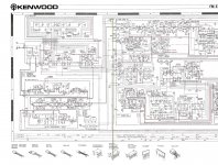
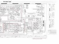
With thanks to HiFi Engine, here's the circuit . (Posts always look better with images). I'll start by swapping in a newer op amp. Not very exciting but maybe enough to make it listenable - which it isn't right now. More later as I get get a chance to learn about it.
Attachments
What Kenwood tuner is that one? TOTL for sure, I am too lazy to look through all the service manuals that I have, KT?
Damn it has a nice RF front end and IF section.
Usually if people complain about a design being flat sounding, it sometimes means it is very low distortion or it has frequency response issues. Before I would recommend to roll op-amps, I'd suggest to replace the ecaps to begin with.
I have a KT-8300 pcb, I noticed that they did not do a very good job of de-coupling the supplies to the op-amps. They usually get away with this because they were using old/slow op-amps. Putting newer, faster op-amps in there could cause them to oscillate unless you use proper decoupling. Even then the return ground traces are very long, meaning lots of inductance. They are single sided pcbs after all.
If you want warmth, it is easy to add distortion, just use a HA1137 FM IF system with the usual quad coil, as they use in cheaper tuners.")
Damn it has a nice RF front end and IF section.
Usually if people complain about a design being flat sounding, it sometimes means it is very low distortion or it has frequency response issues. Before I would recommend to roll op-amps, I'd suggest to replace the ecaps to begin with.
I have a KT-8300 pcb, I noticed that they did not do a very good job of de-coupling the supplies to the op-amps. They usually get away with this because they were using old/slow op-amps. Putting newer, faster op-amps in there could cause them to oscillate unless you use proper decoupling. Even then the return ground traces are very long, meaning lots of inductance. They are single sided pcbs after all.
If you want warmth, it is easy to add distortion, just use a HA1137 FM IF system with the usual quad coil, as they use in cheaper tuners.
What Kenwood tuner is that one? . . . .
Usually if people complain about a design being flat sounding, it sometimes means it is very low distortion or it has frequency response issues. Before I would recommend to roll op-amps, I'd suggest to replace the ecaps to begin with.
It's an L-01T.
Yes, I plan to update some of the electrolytics as well. There are a few who have posted online about doing parts upgrades on this tuner and report benefits from changing some of the transistors as well as the NJM opamps, but I'm not keen on parts rolling as a passtime. I'd like to learn from what I'm working on (if it's not too far over my head) and right now the circuitry itself is what I need to study.
So, why did I get focused on the pulse count detector? Mostly because of this post by one of the earlier contributors at FM Tuner Info.
"Most pulse-count FM demodulators are used because on the surface they are intrinsically linear without tuned circuits. Further, the lack of tuned circuits and the use of highly reliable digital circuits makes the longevity excellent.
As you may know, the output of such a demodulator contains a pulse train whose duty cycle changes in proportion to the FM modulation (roughly akin to delta modulation). To recover this modulation, this pulse train must be passed through a low-pass filter to remove the pulses while retaining the recovered composite baseband.
Since the typical pulse frequency varies by who designed the circuit and how they are implementing it (e.g., double conversion (Kenwood) or the simpler time delay variant (Accuphase)), I will illustrate the problem with an example.
For example, if one has a pulse train around 700 kHz and the composite baseband extends to 100 kHz, the filter must be reasonably aggressive to provide flat, linear-phase response to 100 kHz while simultaneously suppressing the 700 kHz and associated FM sideband components below the noise level of the demodulator. Noise and adjacencies can cause interference just above the composite baseband region. For example, with a 700 kHz IF, an upper second adjacency can cause a 300 kHz [700 kHz (IF) - 400 kHz (difference between monitored channel and second adjacency)] component to appear in the baseband. This can add to intermodulation distortion of this stage. It is therefore desirable to use a filter which has a cutoff frequency as low as feasible given the 0 - 100 kHz linear-phase requirements. It is further desirable to eliminate coupling caps to ensure low-frequency phase linearity.
One must also eliminate DC offset that is a problem in a number of these pulse counters, including the KT-917.
The use of phase equalization permits the filter to be substantially more selective without compromising constant group delay performance in the passband. If the cutoff frequency of the filter is increased in an attempt to place the 0 - 53 kHz stereo baseband within the linear-phase region of the filter, without phase equalization, the noise rejection will suffer accordingly. One can place a much more selective filter in place and say goodbye to the SCA channel, but this can cause phase problems in the baseband.
All of this places some significant requirements on the filter that are not met in any of the tuners that I have measured or done circuit analysis on to date. Those requirements are an active filter implemented with an amplifier stage with substantial bandwidth and phase margin to implement a group-delay equalized filter stage. This requires the use of FETs, bipolars with very high Ft specs or really kick-*** high-speed op-amps! Most of the best parts for this application didn't exist when the classic Kenwood, Pioneer, Accuphase and other brand pulse counters were designed. The problem is generally analogous to a DAC I/V stage. Building an expensive and elaborate discrete circuit reduced the desirability of the pulse counter approach, so most used cheap (and inadequate) op-amps for the job.
Secondly, none of the pulse counters that I have seen in home tuners utilize group-delay equalizers to allow the proper balance between bandwidth and phase linearity, on one hand, and filtering on the other. Therefore, they compromise noise, bandwidth/phase, or both.
Thirdly, most firms used very small coupling capacitors to reduce the capacitors' size and cost which compromise bass phase linearity in this stage or, worse, had substantial DC offset messing circuit performance up.
So we have a condition where instead of delivering the "detector holy grail" we have pulse counters with treble and bass limitations, increased noise and distortion, and/or DC offset problems. Using complex test signals that are easy to analyze in the presence of interference proves this premise in the lab. "
If you want warmth, it is easy to add distortion, just use a HA1137 FM IF system with the usual quad coil, as they use in cheaper tuners.
Funny guy!

Yes the L-01T is an exceptional tuner, as far as specs go but it is puzzling that your listening experience is not to your liking. So is it the design itself or is there something out of spec?
It certainly is as sophisticated as you can get for a FM tuner. Good luck fixing it if anything goes wrong.
Looks like hifi engine did not get the specs correct on the L-01T page.
The highly regarded Sansui TU-X1 is much simpler and is hailed as one of the best sounding that has been made, it is a ratio detector with a very low noise post amplifier. It uses the standard Hitachi HA11223 stereo decoder, same as the L-01T.
Trying to improve the L-01T is a challenge, as where do you even begin to start, especially if you say it is flat sounding, which I take as being very low distortion or has some freq response issue. I guess you could try to measure its performance first to determine that it meets specs.
Listening to the Crown FM two, it is not as warm sounding as other tuners that I have. The Sansui G-7500 tuner is really nice sounding, it uses the standard Hitachi HA1137 double tuned quad coil and a older HA1196 stereo decoder.
One of my back burner projects is to make up a few different stereo decoders, to play with and test out, basically the last of the good ones, Hitachi HA11223, Sanyo LA3450, NEC uPC1223c
From what you have quoted, you would think that there is a performance hit, but the L-01T specs are phenomenal.
If it does not meet specs then you have something to work on. If it meets specs, back to where do you begin to start to modify it.
Having test equipment good enough is a challenge as well. Using your ears as a means to verify performance is a stretch.
I do wonder when some says,
"So we have a condition where instead of delivering the "detector holy grail" we have pulse counters with treble and bass limitations, increased noise and distortion"
Does this apply to a L-01T ? If so I do not see this in the specs, so where does it apply?
I guess I could try and measure the Crown FM two that I have and see if it meets the published specs of +/- 0.5dB 30-15KHz.
I better get going on my stereo encoder design since I can only measure very low thd in mono at this point in time.
I wonder if "tubelab" or anyone else would review my stereo encoder design and give me his input if he is interested? If I will start another thread.
Last edited:
I wonder if "tubelab" or anyone else would review my stereo encoder design
I don't claim to be an expert on such things. In fact I have not really dug into them. I spent the first 61 years of my life in South Florida. I listened to FM radio a lot in my younger years, but by the mid 70's there wasn't much on the radio that I wanted to really listen to. I would search out new music on the radio because at the time, that was the only place to find it. As the smaller stations were either bought up by "corporate radio" and the others left the air, I lost interest in listening to radio. I bought a decent Technics tuner used, in the early 80's and I still have it. I haven't even hooked it up here yet.
With thanks to HiFi Engine, here's the circuit
I looked over the schematic, and I see a conventional quadrature demodulator, IC3. It is a Sanyo LA1231 chip. The data sheet is enclosed.
Attachments
I do wonder when some says,
"So we have a condition where instead of delivering the "detector holy grail" we have pulse counters with treble and bass limitations, increased noise and distortion"
Does this apply to a L-01T ? If so I do not see this in the specs, so where does it apply?
Good question. I hope some day I'll have the answers.
In the original post here there are bits at the beginning and end I trimmed off as I was focused on the pulse count circuit.
I looked over the schematic, and I see a conventional quadrature demodulator, IC3. It is a Sanyo LA1231 chip. The data sheet is enclosed.
Thanks for taking a look and the data sheet. 'Just spent the last half hour comparing that, the tuner block diagram and the schematic. I can see I have work to do. LOTS of work to do if I want to understand this thing. Probably more than is worth it.
I mostly agree with you about FM. I've always liked it for all the live in concert stuff that would never be heard again. The CBC has done incredibly well produced live and recorded for air only concerts and recitals but now that most of the stations I like stream on the web there's less incentive for sure.
Going back to the circuit. I'd thought that the terms detector and demodulator were both used for the same thing. Is that chip not part of a larger pulse count circuit?
Looking at the block diagram.
The LA1231 functions as a 3 stage gain/limiter and part of the muting, signal strength indicator circuitry, the actual FM path for demodulation is highlighted in BOLD.
The 10.7MHz IF comes out of the LA1231 on pin 8, into the AN610, which acts as the mixer/LO for the 2nd IF then through a few filters to remove mixing products, then into the pulse count detector for detection.
FM Detection, demodulation are used synonymously.
Similarly, on the transmitter side it is excitation or modulation, take your pick.
I am lucky, I have a commercial free FM station, all rock/pop thank god, so that is all I basically listen too, CFGI. They are actually getting setup to stream on the net, so everyone is going to be able to hear them shortly.
I don't know where the negatives on the pulse counter detector came from. Done well, which is not hard, its extremely linear. You need the double conversion to move the carrier frequency down to where the circuits work. Its even used in some phase noise test sets. The trick is a very stable one-shot in effect. The DC usually is used for AFC in FM tuners. You may have some offset over time as components drift.
Where would this group delay equalizer go? usually that function would be part of the IF filter i believe.
Where would this group delay equalizer go? usually that function would be part of the IF filter i believe.
The 10.7MHz IF comes out of the LA1231 on pin 8, into the AN610, which acts as the mixer/LO for the 2nd IF then through a few filters to remove mixing products, then into the pulse count detector for detection.
I admit that I didn't really dig into the schematic, I looked it over and saw the quadrature coil, followed it to IC3 and assumed the rest.
negatives on the pulse counter detector came from. Done well, which is not hard, its extremely linear.
That's true, and it can be done several ways today, with the most common being inside a DSP. A well done Phase Locked Loop (commonly called PLL) can do a very good job as well. In the early 80's I designed a commercial quality analog C band satellite TV receiver that did well in the "big dish" home satellite market until signal scrambling came. The receiver used dual conversion to tune the 3.7 to 4.2 GHz band and convert to a 70 MHz IF. The analog FM TV channels were 20 MHz wide and most ran several FM subcarriers for sound and data, pretty much filling the channel. In this case the peak deviation is a significant fraction of the IF, so demodulation becomes more difficult. Looking at the broadcast quality receivers of the day revealed that there seemed to be a roughly equal mix of pulse counters, PLL's and conventional quadrature detectors. I used a high speed divider to divide the IF down to 35 MHz so that I could use the TTL chips of the day to build a PLL.
Today, I am in the early design stages of a multi band receiver that needs to demodulate AM, FM, SSB and the common digital modulation schemes used in amateur radio transceivers. I will use multiple conversions depending on receive frequency to arrive at a very low frequency IF, somewhere around 20 to 30 KHz so it can be digitized by an audio 24 / 96 ADC. The digitized IF goes into an ARM chip, where I get to learn new software skills
That sounds like an ambitious receiver. You aren't using SDR? That would be a lot of software skills to pick up, however there is a lot of existing open source software to draw upon. I had but may have discarded a couple of EMI receivers with continuous coverage from 500 KHz to 1.2 GHz at extremely low levels. big heavy monsters with an array of batteries. I think they were all triple conversion with front ends that borrowed from old turret TV tuners. Except for shielding issues a modern spectrum analyzer can do almost as much in a small hand held package.
Start up a new thread and I would be interested to follow how you are coming along with your concepts and implementation details. There maybe others that have already done this or have years of experience to offer advise. Sorry but that does not include me with the years of this sort of software knowledge.Today, I am in the early design stages of a multi band receiver that needs to demodulate AM, FM, SSB and the common digital modulation schemes used in amateur radio transceivers.
So where do we put RF designs in the forum anyways.
Looking at the block diagram.
The LA1231 functions as a 3 stage gain/limiter and part of the muting, signal strength indicator circuitry, the actual FM path for demodulation is highlighted in BOLD.
The 10.7MHz IF comes out of the LA1231 on pin 8, into the AN610, which acts as the mixer/LO for the 2nd IF then through a few filters to remove mixing products, then into the pulse count detector for detection.
FM Detection, demodulation are used synonymously.
Similarly, on the transmitter side it is excitation or modulation, take your pick.
I am lucky, I have a commercial free FM station, all rock/pop thank god, so that is all I basically listen too, CFGI. They are actually getting setup to stream on the net, so everyone is going to be able to hear them shortly.
Thanks for the confirmation.
Ever listen to CJRT? Years ago it was a great station. Don't know if it was from their front end electronics or the old GE transmitter but the sound was noticeably better. Even in a car you could hear a big difference between them and other FM local stations.
- Status
- This old topic is closed. If you want to reopen this topic, contact a moderator using the "Report Post" button.
- Home
- Design & Build
- Equipment & Tools
- Attenuator DC-RF