Probably the more compact layout is helping a bit.
I agree! Very nice layout work you did there.
")
It wasn't my layout design, marce showed how he would do it earlier in this thread, so I just copied that and added the amp stage. I wouldn't be able to come up with something as neat.
Ahh - that is why it worked!
I remember Marce saying he did board layout professionally. Experience definitely makes a difference. Well good work on the implementation of that design then! I remembered today whay the capacitor stack for the set capacitor on the V4.0 board. 0.047uF at 25V is the largest MLCC available in COG, and in 1% and 2% versions. In the previous tests with the Fliege on the V3.0 board there was a benefit - can't remember what it was at the moment - in chosing an R + C frequency "set" pair that had lower impedance at the notch frequency (bigger cap value).
nice work.thanks for sharing.
I tried AD8066, FET input, which can also be stable without the feedback capacitor.
but the THD seems large which can not be acceptable, especially the input signal peak-peak amplitude is more than 1v. So the active Twin-T notch filter may be much better.
"I consider the Twin-T to be the best overall filter type for an active design, despite its relative complexity, because feedback is used only to raise the filter Q in other feedback filter forms, which use algebraic summation, feedback is used to tune for both phase and amplitude matching, and my experience has been that this raises low-order
distortion products. " -- by Dick Moore
I tried AD8066, FET input, which can also be stable without the feedback capacitor.
but the THD seems large which can not be acceptable, especially the input signal peak-peak amplitude is more than 1v.
Thanks for the information about the AD8066! I'm pretty sure I haven't tried that one. In fact, I don't think I even knew that chip existed. Pretty interesting! It is over 100MHz like the original chip TI suggested in the article. I'll have to get some of those and mess around.
I agree about needing low THD. That is pretty much where I'm at with the Hall Notch filter I have going in another thread here. Great notch rejection but awful THD, according to the QA401 analyzer anyway. I may be doing something wrong there though, either with the measurement or the filter. I haven't gone back and tried to figure out why the additional harmonics yet.
It does have me thinking passive! Passive Hall notch or like you say passive Twin T notch. I would gladly sacrifice some notch depth for "clean" pass-through THD through the filter.
Last edited:
Hi all,
I wrote an article about a Fliege Notch filter for ELEKTOR. (https://www.elektormagazine.com/magazine/elektor-272/60926)
You can download the layout files there.
I also have PCBs for the filter and the power supply.
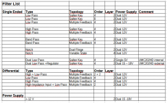
Please find attached a list of filter PCB I did, in case somebody is interested.
Then I can provide detailed information.
Alfred
I wrote an article about a Fliege Notch filter for ELEKTOR. (https://www.elektormagazine.com/magazine/elektor-272/60926)
You can download the layout files there.
I also have PCBs for the filter and the power supply.
Please find attached a list of filter PCB I did, in case somebody is interested.
Then I can provide detailed information.
Alfred
Attachments
- Home
- Design & Build
- Equipment & Tools
- Fliege 1kHz notch filter project PCB